
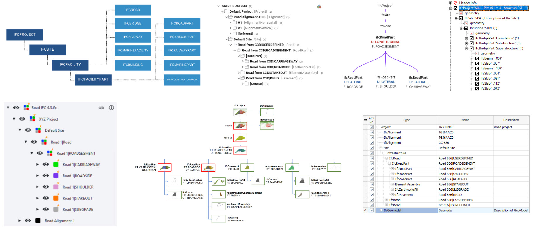
The IFC (Industry Foundation Classes) format has become the foundation of open BIM because it provides what the classic DWG never guaranteed – neutrality, standardization, and rich information. DWG is a CAD format, primarily focused on geometry and technical drawings. IFC, on the other hand, is a neutral, open ISO standard designed to store both geometry and the full context of information about objects.
Why IFC?
It can be treated as a common language in projects where multiple disciplines and software tools are involved – IFC is understood by almost all CAD and BIM applications, which makes it a proven format for collaboration and data exchange.
Importantly, IFC offers great flexibility – you can limit yourself to basic concepts (e.g., wall, slab, window), or use its full potential: classifications, grouping, material assignments, scheduling, costs, or asset lifecycle information. Thanks to this, IFC works in every stage of a project – from conceptual design, through detailed design, to facility management.
Another advantage is that IFC is increasingly required as the standard delivery format. Free viewers (e.g., BIMVision, Solibri Anywhere) make it accessible to all project participants without specialized software. IFC is not just geometry but also relationships between objects, parameters, attributes, and connections – exactly what modern interdisciplinary collaboration needs.
What is this article about?
1. Standards and file organization

2. Layers and information encoding
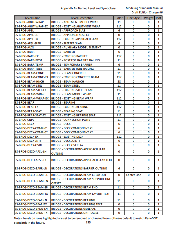
Layers (Levels) are the fundamental organizational structure in DWG/DGN files and determine the logical division of elements. Each layer should correspond to a single object type (e.g., walls, doors, windows), and names should be clear and consistent.
Additional information is often encoded in the layer (level) name itself – usually separated with underscores _, e.g., WALL_CONCRETE or DOOR_METAL_SINGLE. This method allows encoding not only the object type but also its characteristics (material, variant, function).
During migration, you must decide which data is relevant and should be mapped to IFC. The object type will be mapped to an IFC class (e.g., IfcWall, IfcDoor), while the material – instead of being a simple attribute – should be linked through the IfcMaterial class. This is where the process of translating CAD layers into IFC logic begins.
3. Geometry
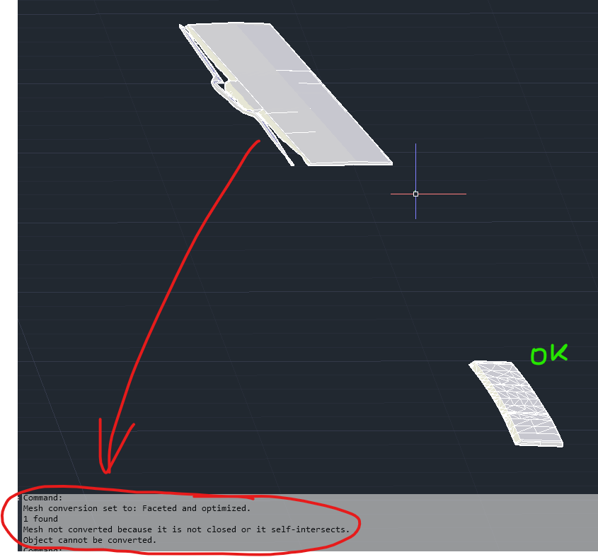
DWG models contain different types of geometry: solids, surfaces, curves, or points. Each must be validated. Solids should be closed and error-free, surfaces should be watertight, and curves or points must have a defined meaning if they are essential for the model. It is also critical to ensure geometry is positioned correctly in the coordinate system.
How to check this? In AutoCAD, you can use commands such as CHECK and AUDIT to detect errors in 3D solids, PROPERTIES or export to SAT to confirm whether an object is a solid or just a surface. For surfaces, SURFSCULPT can be used to attempt creating a solid – if it fails, there are gaps. Curves and polylines can be cleaned with OVERKILL, while points must be reviewed to determine if they are necessary or just auxiliary.
4. Structure and models
5. Quality check
6. Preparing for mapping and attributes
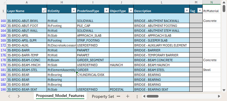
At this stage, you prepare a mapping table showing how DWG layers will be transformed into IFC classes. Layer names are often descriptive and separated with underscores _ (or -), making them easier to interpret.
For example, the layer WALL_CONCRETE would be mapped to IfcWall, while the fragment “CONCRETE” becomes information about material, which in IFC is represented not as an attribute but as a separate IfcMaterial class. Similarly, DOOR_METAL_SINGLE could map to IfcDoor, with the material steel (IfcMaterial “Steel”) and an additional property describing the leaf type.
Furthermore, you can assign other key IFC attributes such as PredefinedType, ObjectType, Description, or Tag. If this information is encoded in layer names or notes, it can be extracted and used. This way, the resulting IFC model is not just geometry but a rich semantic structure useful for cost estimation, energy analysis, or facility management.
7. Trial migration
Before migrating the full project, it is good practice to run a trial migration on a limited scope – for example, one floor, one section, or one discipline. This test helps verify whether the mapping works as intended and whether geometry and attributes transfer correctly.
The process of trial migration involves importing the CAD model into a tool capable of CAD-to-IFC conversion, assigning objects to IFC classes, enriching them with properties and materials, and finally generating a test IFC file. At this stage, it is important to check not just the geometry but also whether attributes such as PredefinedType, ObjectType, or Tag were properly transferred.
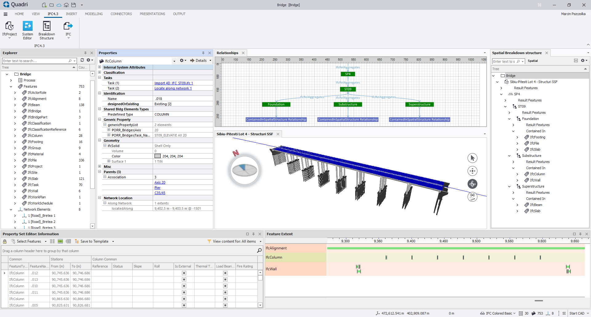
An example of a tool that supports this process is Trimble Quadri, which enables CAD import, mapping objects to IFC classes, enriching them with properties and structure, and exporting a test IFC file. Trial migration helps detect errors early and optimize the workflow before migrating the entire project.
8. Properties and materials
The final IFC model should include both geometry and properties, with assigned materials. Each element must have a name, type, and GUID, while material should be linked via the IfcMaterial class. For example, a wall is not just described by single class but IfcWall + IfcMaterial “Concrete”, and a door is IfcDoor + IfcMaterial “Steel”. This makes the model suitable for analysis, cost take-off, and facility management.
9. Developing SBS (Spatial Breakdown Structure)
Every IFC model must be placed within a logical spatial structure – SBS. Elements should be assigned to a project, building, storey, or space (IfcBuilding, IfcBuildingStorey, IfcSpace).
Tools like Trimble Quadri can assist in structuring data within SBS, making the exported IFC file not only geometrically correct but also properly organized with information hierarchy.
10. Coordinate Reference System (CRS)
Summary
Migrating CAD models to IFC may seem complex, but with proper preparation and a step-by-step approach, it is possible to avoid common pitfalls and create an information-rich model. The key lies not only in correct geometry but also in properties, materials, and spatial structure, which make IFC a powerful tool for collaboration in BIM projects.
I encourage you to try out the methods described and explore more of our articles on BIM Corner, where we share practical knowledge about BIM and digital project workflows.
See you in the next article!