
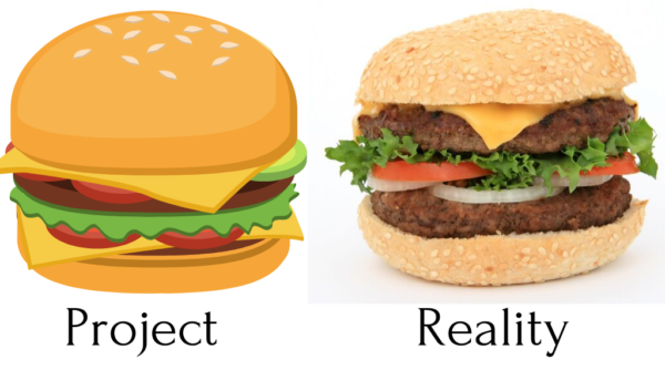
The abbreviation BIM, derived from the words Building Information Modelling, is an idea focusing in one place the attention of all the construction process participants included in the project. BIM technology supports viewing and information processing. The people involved in the project can monitor and analyze the project from different perspectives while having a wider and more accurate point of view. The multi-discipline BIM model represents the heart of the project. Adequate interpretation and understanding of the project, as well as the cooperation of all parties (Investor, Designer, Contractor) at each stage of the investment, contributes to increased quality of documentation and reduction of risk associated with the exceeding of the assumed investment time.
In the following article, I will describe my observations concerning the differences in work on projects implemented under the traditional method (based on technical documentation) as well as those based on the BIM model. Briefly writing CAD vs BIM. The observations will be grounded on the experience gained in working with infrastructure projects in Norway during 2014-2019.
Table of Contents
- CAD vs BIM: Design method
- CAD vs BIM: Project data / file structure
- CAD vs BIM: Input data / existing situation
- CAD vs BIM: Collisions in the project
- CAD vs BIM: Object consistent with the project
- CAD vs BIM: Administrative matters
- CAD vs BIM: Printing style
- CAD vs BIM: Communication in the project
- CAD vs BIM: Mulit-Branch consultation / Descisions in the project
- CAD vs BIM: Modifications in the project
1. DESIGN METHOD
TRADITIONAL DESIGN METHOD
Many design offices still provide CAD-based technical documentation (e.g. AutoCad, Macrostation). The CAD design is nothing more than drawing a project in a digital form. Developments such as plan layout, longitudinal section, and cross-sections are created in separate drawings. Lack of correlation between drawings is therefore laborious. In such a perspective, each of the drawing elements is static: if we intend to make a change in the design, it requires manual intervention in each drawing separately, which prolongs the time of documentation preparation and increases the risk of inaccuracy. Additionally, the amount of waste (paper) is significant.
DESIGN BASED ON THE BIM MODEL
Creating projects supported by BIM tools brings many benefits. For example, by modeling a road corridor in 3D, we develop many smart objects related and geometrically dependent. For instance, by optimizing the geometry of a longitudinal profile, we notice how transformations affect other related elements. Additionally, BIM software supports you in automating many repetitive design tasks. This is due to the parametric programming language and the smart nature of the objects. Parametric programming tools (Dynamo, Grasshopper), combined with Civil 3D design applications, offer even more possibilities than ever before. Thanks to the parameterization, we can increase the number of variants of the solution by reducing the design time. Thus, we can choose the most optimized solution. Currently, the most frequently used parametric design is applied in bridge projects, e.g. Tekla+Grasshoper.
2. PROJECT DATA / FILE STRUCTURE

TRADITIONAL DESIGN METHOD
Data and information are provided in the form of drawings, scans, photographs, reports, letters and paper versions of drawings. Project data is stored on a local disk. Frequently, there is no fixed folder structure, file name, drawing layer, or drawing numbering. It is possible to work with outdated data and waste time looking for the latest version of a drawing.

DESIGN BASED ON THE BIM MODEL
BIM data have different formats and origin. Among other things, data is stored on a cloud server. Appropriate naming, file structure (WBS Work Breakdown Structure) or folder structure gives new possibilities of data update. For instance, an IFC file containing a road model (e.g. 01_r1_300.ifc) stored in a properly named folder can be easily located and updated from a folder using a script which performs the entire operation for us in the background (Navisworks).
In the project I am currently working on, we are using RPA technology (Robotic Process Automation). It allows you to save 40 hours a week when exporting data and updating the model. IFCs are exported directly from the software without any designer intervention and then updated in the main multi-discipline model (Navisworks).
It is precisely the proper naming and file structure that enables data update and smooth data flow even without access to API (Application Programming Interface).
3. INPUT DATA / EXISTING SITUATION
TRADITIONAL DESIGN METHOD
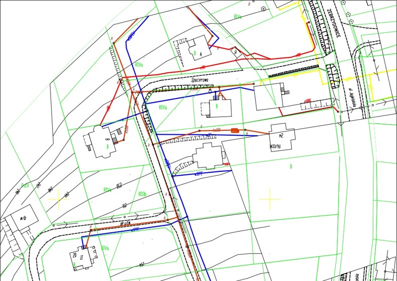
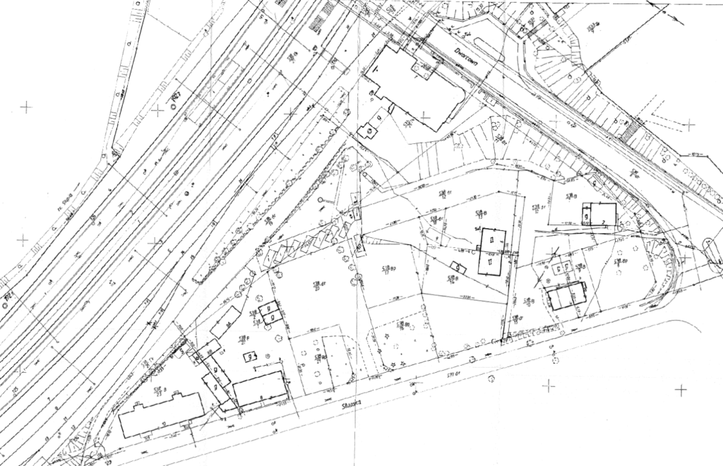
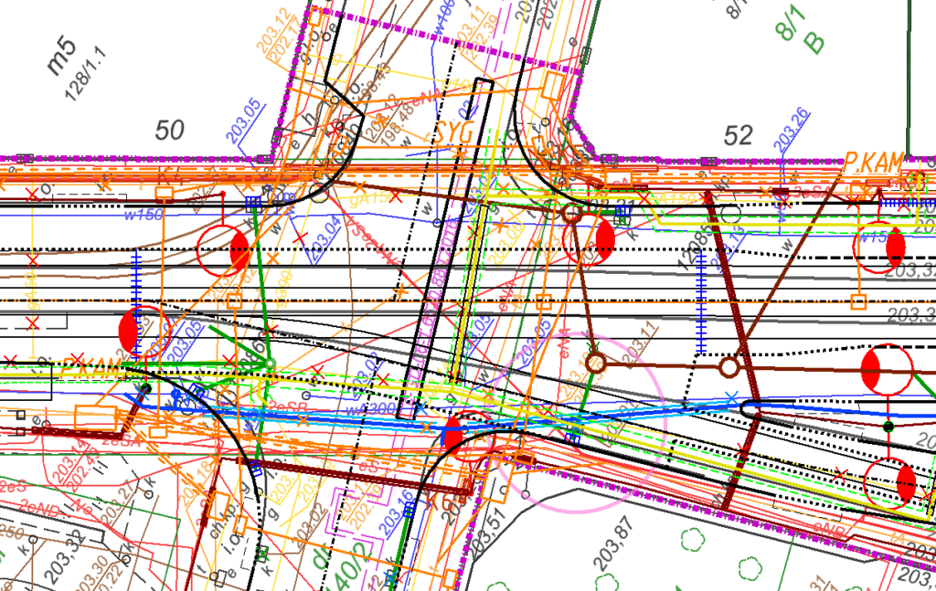
The input data consists mostly of 2D vector maps (scans of paper maps are common) presenting the existing road situation, land registration, underground infrastructure networks and land surveying in characteristic points of the route.
The inaccuracy of the data results in a large number of deviations and an increased cost of the project. It is due to time-consuming corrections in the project or even repair works on the construction site.
DESIGN BASED ON THE BIM MODEL
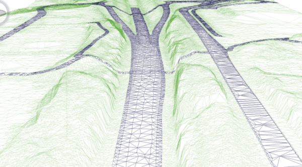
The input data is fundamental for multidiscipline collaboration. Raw data represent the existing situation in the form of points, lines, point clouds or surface areas. The product typically used to calculate the discipline models is the DTM terrain model (Digital Terrain Model). The accuracy of the data depends on the type of project. The more complex the object, the more accurate the data is. The data represents the existing situation, but also includes a model of underground layers. BIM model also consists of GIS (Geographic Information System) data and geotechnical data. It is common practice in Norway to create DTM models of underground strata based on geotechnical drilling. Furthermore, the project features a specific CRS (Coordinate Reference System).
4. COLLISIONS IN THE PROJECT
TRADITIONAL DESIGN METHOD
Documentation prepared based on technical drawings poses a high risk of a multidisciplinary collision. The reason for this is the low accuracy of the data and the limited capabilities of the collision checking tools. In simple terms, the collision is examined in a flat 2D drawing.
DESIGN BASED ON THE BIM MODEL
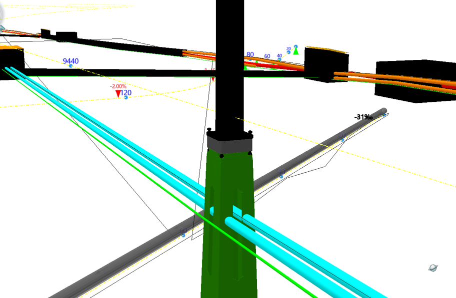
The existing and newly designed situation is modeled in 3D. 3D models of individual discipline and terrain model are combined in one multidiscipline model. The model is contained in software allowing to store and display objects in a graphic and non-graphic form (e.g. Quadri). In the initial phase of the project, the model is subjected to visual inter-branch evaluation. Along with the development of the project phase, conflict control is performed in the appropriate tool (e.g. Navisworks). The ability to automatically capture conflicts at the design stage saves money, time and reduces repair work at the final stage of the project.
5. OBJECT CONSISTENT WITH THE PROJECT
TRADITIONAL DESIGN METHOD
The large area and complexity of the project mean that many objects may be simplified. The building does not reflect the paper version of the object in 100%. Bill of quantities and cost estimation relying on drawing documentation is of doubtful quality. They are frequently visual and result from significant deviations detected only at the construction stage. Underestimated amounts of materials may appear on the construction site. Major discrepancies prevent proper control of investment costs by the ordering person and the building manager.
DESIGN BASED ON THE BIM MODEL
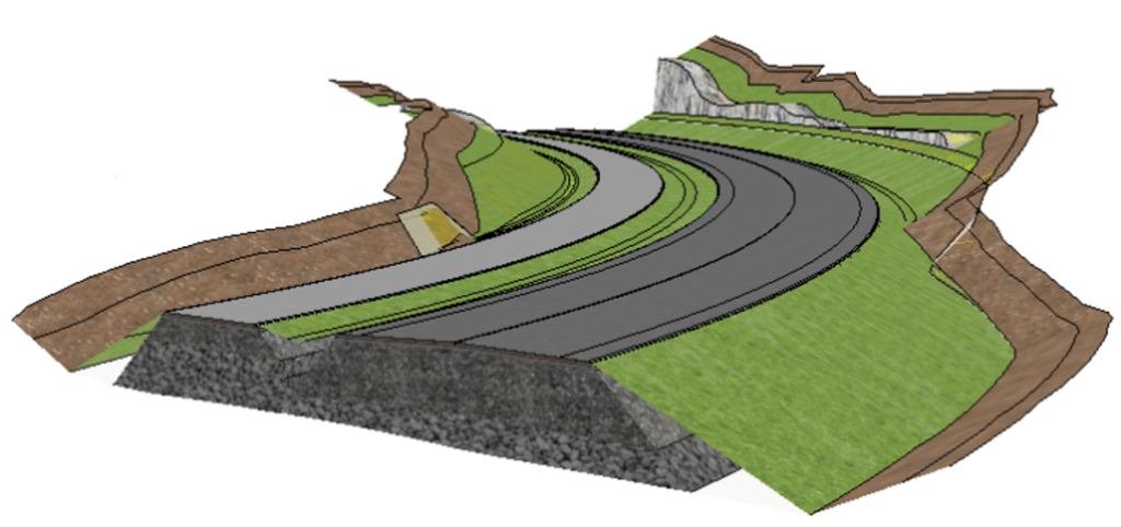
Digital twin reflects the building under construction. The discipline model is generated based on a detailed terrain model (DTM).
The terrain model takes into account the existing situation, but also the model of underground layers. 3D industry models allow for accurate estimation of earthworks and materials. Modern tools can generate reports and set the number of existing elements, earth masses as well as materials.
The key information of the graphic object is the volume, which due to the large diversity is simplified and not applied in the traditional method.
Also, digital data is sent directly to the construction site, and machines with appropriate information processing systems “build along the path” e.g. an embankment (e.g. a grader forms a road embankment).
6. ADMINISTRATIVE MATTERS

TRADITIONAL DESIGN METHOD
The designer influences the technical part of the project, in the context of its execution time. The other components of the project documentation, such as administrative matters, agreements, permits, depending on the functioning of the authorities and the competence of the stakeholders. The time necessary for obtaining permits and paperwork is different from the area in which the designer provides services.
Competent individuals in the project are essential.

DESIGN BASED ON THE BIM MODEL
The idea behind BIM is to involve people responsible for administrative matters in the project from the very beginning of the investment.
This is particularly well done in Norway, where public administration is an active member of the whole investment.
The administration in the form of the Nye Veier organization has an insight into the project processes, which allows it to make decisions faster and more efficiently, thus shortening the time of project implementation. Industry specialists working in the administration who know BIM are the key to success.
7. PRINTING STYLE
TRADITIONAL DESIGN METHOD
Often, the time required to prepare drawing sheets exceeds the time it takes to find the right design solution. Elements such as line thicknesses, colours, descriptions, layer names, fonts, scales, and tables are determined following your preferences. It is easy to neglect standards. Additionally, each company has its printing style. Lack of consistent guidelines on the way paper documentation should look like makes it difficult for the contracting authority and the building manager to interpret it.

DESIGN BASED ON THE BIM MODEL
Managing print styles offers a great advantage of applying BIM software. The software includes ready-made templates which can be adjusted to your requirements. We may change the colour and texture of 3D objects, but also the appearance of lines or points. Graphic information is related to the object, so in the cross-section of this object, we will also see the texture (cross-sectional fragment). No need to hatch the surface in a 2D view and it saves us time.
The trend reveals that the drawing documentation will soon be out of circulation. If necessary, with a few clicks we can generate the entire drawing documentation on the appropriate scale and view it from the tablet. (Novapoint)
8. COMMUNICATION IN THE PROJECT

TRADITIONAL DESIGN METHOD
The communication between people in the project in most cases happens via e-mail. A large number of non-standard messages. Contact is isolated and asynchronous. Due to lack of proper information flow mistakes appear in the project, which increases the risk of later corrections

DESIGN BASED ON THE BIM MODEL
As a result of working on a single multidiscipline model, all people in a project can communicate within it employing an appropriate tool created for such a purpose.
For the communication purposes compatible with openBIM, it is worth considering the BCF format (BIM Collaboration Format). BCF contains a message in the form of a photo (Viewpoint) and text information, e.g. a comment. Messages are simple to analyse thanks to appropriate tagging (e.g. #road, #electro #conflict). Correctly described messages may be quickly found and returned to the breakthrough moment in the project with the help of a timeline.
The AGILE methodology, known from the world of IT (software development), improves the management of project messages. For example, a message can be treated as a thread. Every thread from every person is collected to a common system, where anyone sees all the arising threads and above all those for which they are responsible. The thread (e.g. “move the ditch”) can be assigned to the person responsible for the road model and subsequently on the Kanban board moved between the TO DO-IN Progress-QA-DONE tabs.
9. MULTI-BRANCH CONSULTATION / DECISIONS IN THE PROJECT
TRADITIONAL DESIGN METHOD
Industry consultations are conducted based on paper drawings containing changes, comments, etc. A technical drawing limits the possibility of spotting potential dangers and risks at the design stage. Lack of tools and properly prepared materials prolongs the time of decision making.
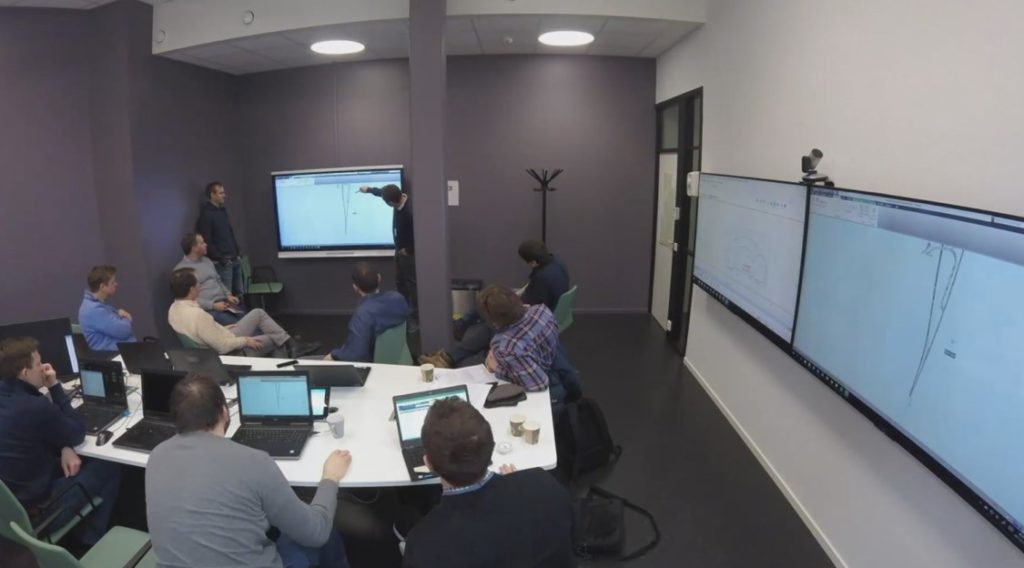
DESIGN BASED ON THE BIM MODEL
Working on a single multidisciplinary model and understanding the interdependencies between industries is the foundation for decision making in a project. Multidiscipline meetings are held in the form of ICE (Integrated Concurrent Engineering) sessions. During the meetings, modern technology is employed to display the BIM model in a room on large interactive screens. The meetings provide a 100% attendance of decision-makers in the project in one place and time. Meetings are held regularly, e.g. every 2 weeks with a scheduled up-to-minute agenda. An important role is played here by BIM Facilitator, who leads the meeting and supervises its course. During the ICE session, the key decisions for the project are taken.
10. MODIFICATIONS IN THE PROJECT

TRADITIONAL DESIGN METHOD
Introducing modifications to the project generates additional time. The more advanced the project phase, the higher the cost of the modification. A practice applied during multidisciplinary meetings includes lobbying for project solutions. Experienced designers, acting in such a way, avoid laborious changes in the project. Unfortunately, such tricks often result in the doubtful quality of documentation, as the designed variant is not properly analyzed.

DESIGN BASED ON THE BIM MODEL
The maturity of the industry model in terms of the overall project is regularly analysed based on the MMI (Norwegian: Modell Modenhets Index). The MMI index supports, among others, the monitoring of the progress of projects/engineering works and also represents one of the numbers 100-200-300-350-500. MMI combines LOD (Level of Development/Detail) and LOI (Level of Information). It also includes information such as risk level (e.g. correct volume of the construction layer) and information application area (e.g. staking data, visualization).
The MMI allows for improved planning of deliveries as well as reduces the risk of mistakes through a precise analysis of the schedule.
Summary
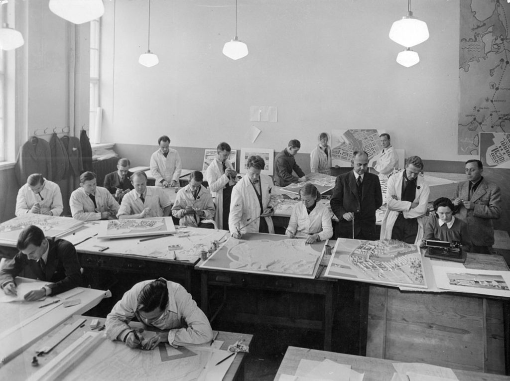
Traditional methods mean that the designer spends a considerable amount of time creating paper documentation. A common information management system is missing. The method and the way of creating technical documentation influence the quality and determines the valuation of design services. The time of project implementation depends on the area of service provided by the designer. An old design school prevails here and designers benefit from a traditional college-educated technique, which does not necessarily correspond to current market opportunities.
From the above list, it is clear that the application of BIM technology in road design provides considerable benefits for both designers, ordering parties and other entities involved in the construction process. Working with BIM involves the implementation of the latest technologies, which significantly minimize the human factor as a source of error and unnecessary costs. However, it is not about displacing people from the labour market – modern tools currently offered by the technology are only to improve our daily work. As an integral part of our everyday work, it contributes to the increase of our effectiveness.
Design methods are considered as the first candidate for change in the context of working with BIM. The information structure and division of the project is crucial in terms of automating the processes occurring in the project. BIM technology is suitable for different locations but does not have to be implemented in 100%. BIM comprises 90% of processes and 10% of tools. It is worth focusing on improvements in your company and start applying the term BIM as the main idea signaling change. It is also worth noting the decreasing distance between the IT world and the construction industry. We call it the digitalization of the construction industry, where BIM is one of the leading factors.
In the following articles, I will focus on the development of the various aspects mentioned above.


Thank you Marcin, you have me on the bright side, and it is really hard to understand, that BIM is not an official requirement in public tenders in most of countries. How to explain this?