

In my previous post about Open BIM, I showed you a requirement table example. We explored how proper IFC properties transform chaotic information exchange into something manageable.
But here’s the catch: even when you know what data you need, traditional documentation creates its own problems. Excel spreadsheets and PDF documents fail at what matters most – making sure the right information actually gets delivered correctly.
Manual Quality Assurance Nightmare
Back then, we manually checked every IFC export against requirements. I still remember spending entire weeks with Solibri, creating data validation rules and clicking through hundreds of issues. Half of them were duplicates I couldn’t drop.
It was exhausting and error-prone.
Without automated validation, teams struggle with:
- Manual verification of model data against specifications
- Subjective interpretation of “correct” information
- Late discovery of missing or incorrect data
- Software that barely verified anything beyond physical clashes
Updates Were Nearly Impossible
When requirements changed mid-project – and they always did – updating those Excel files became a coordination nightmare. We had to notify every discipline, check if they understood the changes correctly, and manually verify implementation. Information often got lost in translation.
Communication Ambiguity
Traditional information requirements shared through Excel sheets or PDFs are difficult for the right people to access and interpret consistently. This leads to misinterpretation of requirements across project teams, inconsistent data delivery between stakeholders, and time-consuming manual validation processes.
The Solution
Thankfully, around one year ago, the BuildingSMART came with a solution to these pains. A solution that is open, free and automated.
And easy to implement both on a project and by software vendors.
Interested?
Let’s understand Information Delivery Specification.
What is IDS (Information Delivery Specification)
Information Delivery Specification (IDS) is a buildingSMART standard that defines information requirements. IDS provides a structured XML-based format that humans can read and computers can interpret and process automatically.
At its core, IDS specifies exactly what information must be delivered in BIM models and how it should be structured. It enables precise definition of requirements for IFC objects.
An IDS file can contain multiple independent requirements. Thanks to this, you can copy-paste these blocks between various IDS files.
What IDS changes
Information Delivery Specification is machine-readable. The computer understands what you need. No more room for interpretation like they probably meant this.
Software knows exactly what to check.
Here’s the workflow:
- You create requirements in an IDS
- Upload a model and IDS file into validation software
- Software checks the model against uploaded IDS
- You get an issue report
No manual clicking, no guessing.
Plus: it’s an open standard. Free, available to everyone, supported by growing number of BIM tools. Anyone can use it today.
Benefits for your team:
- Asset owners specify precisely what they want
- Project teams see clearly what they need to deliver
- Validation runs automatically
- Data validation became available in multiple software now!
What IDS is not for
IDS is powerful, but it’s not created for everything. Understanding its limitations matters.
IDS cannot:
- Create ambiguous conditions (e.g. I need enough fresh air volume in that room). You have to be specific with a range in cubic meter per hour or air change rate)
- Define design requirements (components distance, free opening area, lighting analysis, etc.). IDS can require data, not geometry.
- Create nested rules for multiple object types (e.g. if the space is escape route then the doors have to have Fire rating). You need to create separate specifications for that.
IDS File Structure
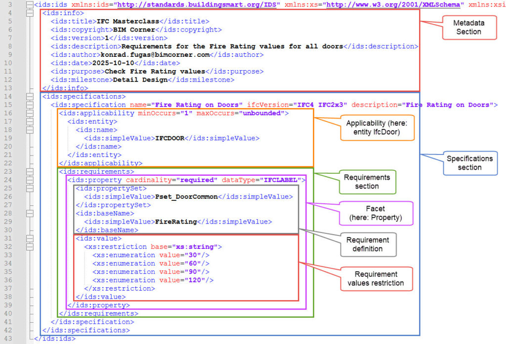
IDS files use XML format, ensuring data works for both humans and computers. The structure follows XML standards.
An IDS file consists of two primary elements:
Metadata Section
Contains general information:
- Title, version, author, creation date
- Description and purpose of requirements
Specifications Section
The core of the IDS file where all requirement blocks are defined.
Applicability (The Filter)
The applicability section defines which elements from the IFC model should be selected for checking. It works as a filter applied to the whole IFC model.
We can filter elements by type, properties, classifications, or other criteria called \”Facets.\”
Examples in human language:
- Show me all walls from the model
- Show me walls, doors and windows that have a fire rating
- Show me walls, beams and columns made of concrete
- Show me all objects that are load bearing
Requirement (The Rules)
Specifies what conditions the selected (filtered) elements from the applicability section must meet.
We can specify these requirements to properties, classification, materials, and relations. These are also defined by the same “Facets” as in the applicability.
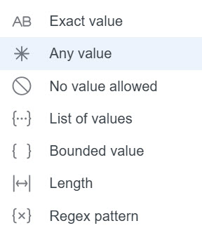
Requirements define the exact information that must be present and correctly formatted. You can specify whether you want:
- Any value
- An exact value (Simple value)
- No value
- List of values (Enumeration)
- Bounds (Range restrictions)
- Length Constraints
- Precision Controls (Decimal Values)
- Pattern (Regular Expression)
Different software helping with IDS creation have implemented different value requirements.
The Six IDS Facets
The term facets comes from XML Schema terminology. In IDS context, facets describe how different aspects of information requirements are structured.
Just as a gemstone has multiple facets reflecting light differently, IDS requirements examine different faces of building information:
- Each facet represents a different dimension of information validation
- Facets can be combined to create comprehensive requirements
- The modular nature allows flexible specification creation
- Multiple facets can apply to the same objects simultaneously
There are 6 different facets in IDS, let me describe them below:
Entity
The Entity facet defines which IFC object types you want to check. This is your starting point identifying the specific building elements to be checked and creates the foundation for further requirements.
Example of definition:
- I want to examine all walls so you are choosing IfcWall
- Let me look at every door in this model then you are choosing IfcDoor
- I want to see all structural elements – you choose IfcSlab, IfcWall, IfcColum and IfcBeam (and maybe IfcMember, or more depending on the building)
Property
This handles all those critical properties that make a model data. Standard property sets you’ll work with include properties from IFC schema Common Property sets as well as Custom Defined Properties.
You can find IFC schema built in properties here: IFC4x3 Common Property Sets.
Example of definition:
- Pset_WallCommon has property FireRating with acceptable values as REI30, REI60 or REI90
- For custom property set: Pset_Manage has property Responsibility that follows the pattern “letter R and 3 digits” (R210). You would write it in REGEX: /^R\d{3}$/
Attribute
Attributes, in short, are fixed, core metadata fields assigned directly to IFC classes. They are consistent and inherited through the IFC class hierarchy.
These are for instance GlobalId, Name, Description.
Example of definition:
Building levels should have name only from this list of values: Level 01, Level 02, … , Level 09.
Classification
This facet handles industry-standard as well as project defined classifications. Examples are Uniclass, Coclass or other national classification standards.
Example of definition:
Coclass classification: all air handling units components have code KP.CD.AC
Material
The Material facet specifies material requirements and properties, defining material relationships and characteristics. This facet ensures proper material specification.
Example of definition:
All structural columns are made of concrete
PartOf
Buildings have structure and hierarchy. This facet validates spatial relationships, ensuring elements are properly contained within buildings and located on correct floors. This is the most advanced facet (and least used).
Example of definition:
- Does every pipe have insulation
- Does each element belong to specific system.
Cardinalities
Cardinalities in IDS are constraints that define whether information requirements are mandatory, optional, or prohibited. They determine the validation behavior for each specification:
- Required – The element, property, or facet must be present. Validation fails if the requirement is not met. Most popular cardinality.
- Optional – The element, property, or facet may be present but is not mandatory. Validation passes whether the requirement is met or not. It might be useful for recommendations.
- Prohibited – The element, property, or facet must NOT be present. Validation fails if the prohibited item is found. Useful for excluding certain configurations or legacy properties.
Example: if the whole project is in LOD350, the prohibited values might be LOD100 and LOD200
IDS example
Available software to create an IDS
The list of vendors supporting IDS creation is already extensive.
I use Solibri since I’m familiar with that software, but the IDS editor is behind a paywall. If you’re looking for free solutions, I’ve heard good words about Acca and BIM Vision.
To check if your favorite software vendor has implemented an IDS creator, visit the official BuildingSMART website for IDS implementations status.
The Future is Automated
The construction industry is moving toward automated quality assurance and machine-readable specifications.
IDS represents this shift: from reactive quality checking to proactive requirement validation. From document-based requirements to structured, enforceable specifications.
What’s your biggest challenge with BIM information requirements? Share your experience in the comments below, and let’s discuss how IDS can solve your specific pain points.