
In the first article in the IFC for Infrastructure series, I mentioned that IFC can be divided into 3 main thematic groups: objects, properties, relationships. I was also able to discuss the first of these topics in it. If you have not read this post yet, I invite you to read it at this link: All you need to know about IFC 4.3 for infrastructure
In this text, I would like to discuss a practical example. Let me present one of the many possible scenarios for the spatial division of the road project.
I invite you to read the article.
CASE STUDY
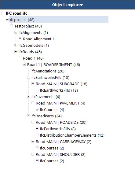
ifcProject
We start the project division from creating an ifcProject entity. At this level we can define the units used in the project, assign a coordination system, indicate the name of the project or the context of the investment.
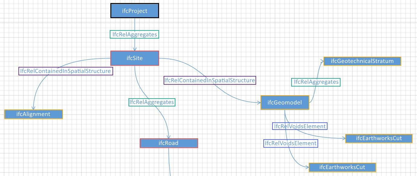
The elements of the spatial structure are linked together by the ifcRelAgrregates relation.
In our example, the elements of the spatial structure are ifcSite and ifcRoad.
Products (ifcProduct) are positioned in the spatial structure using the ifcRelContainedInSpatiatialStructure. In this case it is ifcAlignment and ifcGeomodel.
ifcGeomodel is an abstract that we can think of as a group / set. Contains elements that describe the terrain. The site is presented using ifcGeotechnicalStratum. The ifcRelAggregates relationship was used to add this object to the set. ifcEarthworksCut represents “cut” volumes during road construction that create a void from the terrain. So this object is added to the ifcGeomodel using the ifcRelVoidsElement.
Similar situation occurs in the case of structural walls in a building (ifcWall), when we use this relation ifcRelVoidsElement to cut out the space intended for the door.
ifcRoad
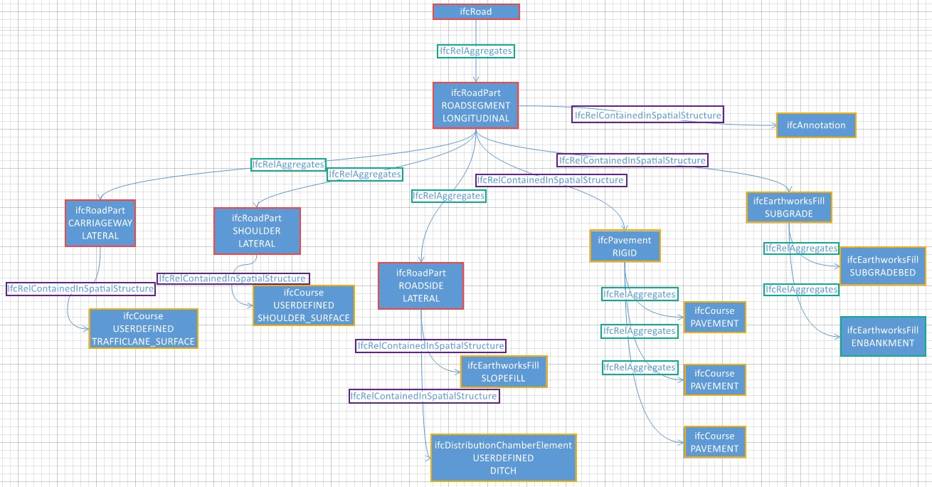
ifcRoad is a spatial abstract representing a road model. In the IFC schema, you can break the road into parts (represented by the ifcRoadPart). The division into parts in the context of a road structure can take place in two main directions: longitudinal and lateral.
In the case of longitudinal road division, we mean the division of the road into segments / sections. The lateral division indicates the division into characteristic parts such as the road, paved shoulder, green shoulder, roadside.
In the discussed example, there is a division in both directions, however, the longitudinal division is at a higher level than the lateral. Usually, we talk about the road in the context of the segment between km X and km Y. For this reason, in my example, the longitudinal division is the superior division. So ifcRoad is linked to ifcRoadPart (Longitudinal) using ifcRelAggregates. This relationship is also found between ifcRoadPart (longitudinal) and ifcRoadPart (lateral).
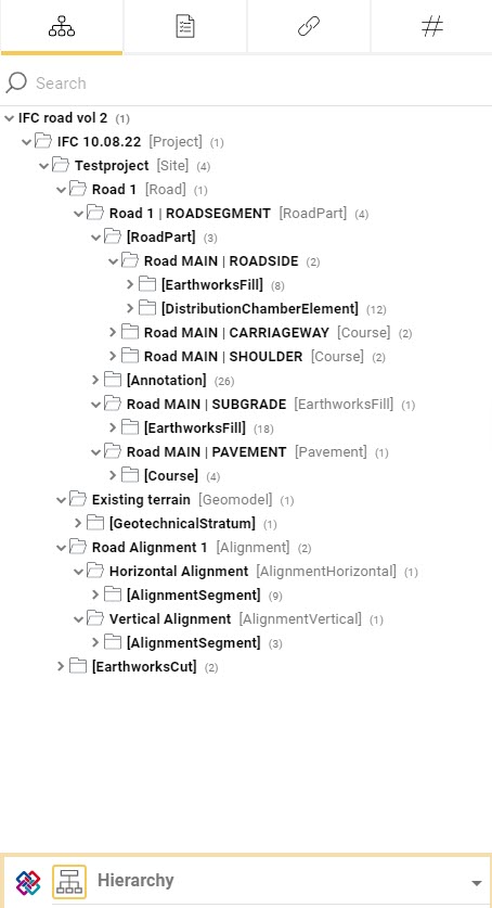
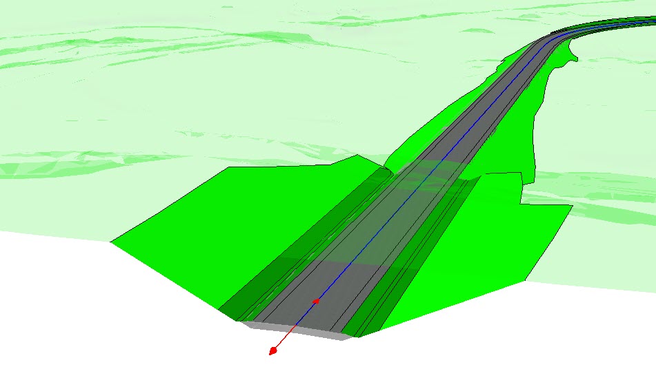
The road along its entire length contains characteristic elements such as an embankment or pavement layers. In addition, from the road model, we can also generate lines representing the edges of individual surfaces.
The edges of the pavement layers, individual components, are important information for surveyors. By using ifcAnnotation we can save this information. These types of lines can be used on the construction site as stakeoutdata. All these objects are in the hierarchy below the ifcRoadPart (longitudinal) and are connected to it using the ifcRelContainedInSpatialStructure relation.
The objects that make up the pavement layers (ifcCourse), using the ifcAggregates relation, are aggregated in the set represented by the ifcPavement abstract.
An interesting example of an class is ifcEarthworksFill, which can be used both as an object and as a collection. In my example, ifcEarthworksFill accumulates objects that describe the fill and the bottom layers of the pavement.
Under the ifcRoadPart (lateral), there are objects that are characteristic of each area in a transverse relation. The discussed road model was created using the Trimble Novapoint software, which generates the top surfaces of the road corridor. In this case, the surfaces along the asphalt pavements are fictitious surfaces. In the BIM model, they are created for visualization purposes (adding texture). However, they can be exported to an IFC file. For this reason, in my example, they are under ifcRoadPart, which describes the road and the shoulder.
On the other hand, under the ifcRoadPart, which describes the roadside, you can find ditch-shaping surfaces (ifcDistributionChamberElement) and slopes (ifcEarthworksFill).
Summary
The above division of the road is inspired by the one suggested by buildingSMART International in its study IFC Road Conceptual Model Report , however, contains additional elements, such as the aforementioned fictitious layers of the road. Remember that road projects may differ from each other, which can directly translate into a project division hierarchy.