The use of clash detection is crucial for ensuring BIM model quality. It is mandatory in certain cases according to Brazilian Federal Decree 10.306 (2020) since 2021.
To ensure BIM model quality in engineering projects, it is important to plan procedures before project execution. This allows the benefits of using the BIM Methodology in construction to be realized.
One effective practice is the use of a Clash Matrix. It:
-
standardizes analyses,
-
facilitates comparison, performance assessment, and decision-making
It is essential to structure methods to develop BIM models that include appropriate engineering solutions and comply with the BIM Execution Plan in terms of graphic and non-graphic information.
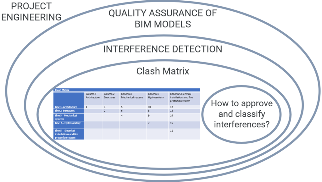
This article presents suggested rules for classifying and approving interferences using the Clash Matrix for BIM Projects.
The article is structured as follows:
a) What is Quality Assurance of BIM Models;
b) Designing and executing a Clash Matrix;
c) Using the Matrix in a project under development;
d) Suggestions for classification rules and approval of interferences using the Clash Matrix for BIM Projects.
2. Development
2.1 What is Quality Assurance of BIM Models
Quality assurance verification involves verifying the accuracy of the information within a BIM model.
To determine the accuracy of the information, it must be compared to a reference, often requirements provided in the BIM Execution Plan.
Therefore, strategies need to be designed and implemented to ensure that BIM models adhere to predefined rules for both graphic and non-graphic properties.
Regarding geometric inconsistencies, several issues can be identified, including:
– Compliance with the project’s base point.
– Conflicts between geometric components.
– Duplications of BIM objects.
– Failure to meet specified Level of Detail.
– Components positioned at incorrect levels.
– Elements modeled in incorrect disciplines.
– Compromised IFC extraction in terms of geometric aspects.
– Model solutions that deviate from real engineering solutions.
– Non-compliant levels and axes in relation to the BIM Execution Plan, among others.
As for information inconsistencies, the following can be mentioned:
– Inadequate georeferencing information in the model.
– Objects with incorrect or generic IFC classes.
– Failure to adhere to the Information Classification System.
– Failure to meet the specified Information Level.
– Compromised IFC extraction regarding non-graphical information integrated into the native model.
– Inappropriate insertion of model properties.
– Incorrect project links
Based on my practical experience, I have found that the most challenging inconsistencies to control are conflicts between geometric components, due to their high frequency and the assumptions that need to be made.
In Brazil, the use of BIM interference detection has been mandatory in engineering project contracts involving the Federal Public Administration since 2021, as stated in Brazilian Federal Decree 10,306 (2020).
To ensure that the generated interference reports from the clash detection process provide real benefits to construction, a well-designed process is required.
In this regard, the development of a Clash Matrix emerges as a crucial tool.
2.2) How to create and use a Clash Matrix?
A Clash matrix is a table that shows the intersections between disciplines, allowing us to determine the sequence for conducting interference detections (clash detections).
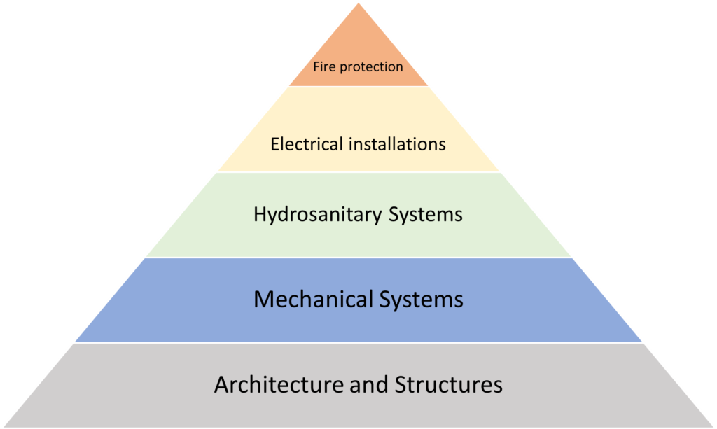
To begin, a hierarchy of flexibility is established among the disciplines.
Disciplines at the base of the pyramid have less potential for flexibility, while those closer to the top have greater potential. The first step is to define the priority for flexibility between project disciplines.
Below is an example of a Clash matrix for building projects (Figure 2).
- Check the status and verify completed works at every stage of your project,
According to Figure 2, we can observe the following situation:
At the base of the pyramid, we have disciplines with the least flexibility, and as we move towards the peak, the potential for flexibility decreases.
For instance:
If there is a conflict between the disciplines of architecture, structure, and mechanical systems, the discipline that should be modified is mechanical systems.
This depends on factors such as cost and effort required to make the change. However, if there is a conflict between mechanical systems and hydrosanitary systems, the hydrosanitary systems should be made more flexible.
This is because mechanical systems typically have larger components, which can present space restrictions and have greater impacts when changed.
In the case of interference between sanitary systems and electrical systems, the electrical systems should be modified.
This is because electrical systems generally have smaller dimensions, and hydrosanitary systems are often linked to specific spaces in the project (such as bathrooms and kitchens), which have limited flexibility in changing their positions throughout the project.
Once the pyramid is created, the order of evaluation for detecting conflicts between disciplines should be considered consistently in all analyses.
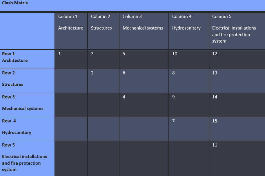
This ensures the quality of the analyses and allows for the development of a standardized and known procedure that can evaluate process performance. For building projects, the matrix may look like this:
Names of project disciplines are located in the columns and rows.
In the first analysis, we take architecture and structures disciplines (column 2).
The second analysis, is column 3, architecture, structures and mechanical systems. It goes as follows:
Architecture vs Mechanical Systems
Structures vs Mechanical Systems
We can use model verification tool, such as Navisworks by Autodesk, to perform a check:
- Test 1: Architecture x Mechanical Systems,
followed by
- Test 2: Structures and Mechanical Systems.
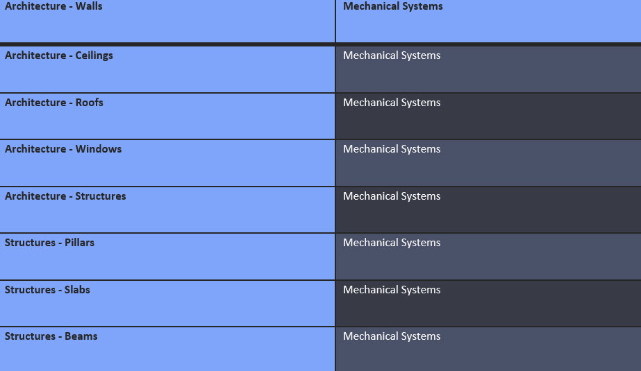
In addition, specific analyses can be conducted within disciplines.
For example, one can examine column 3, as illustrated below:
2.3) How to use the Clash Matrix during a project development?
Once we understand what a Clash Matrix is and how to create it,
It is important design methods and processes to ensure its proper use in contracts that will be executed.
The tool should be designed and executed by the person assigned in the BIM Execution Plan (usually the BIM Coordinator), and meetings should be held with established rules to enhance its usage and discuss the results.
Firstly, it is important to define milestones for receiving the models. The models will be sent by the discipline Leaders and received by the BIM Coordinator.
The BIM Coordinator will be responsible for receiving the models, conducting various checks on both geometric and non-graphic information, and leading BIM coordination meetings to discuss the results for appropriate classification and approval.
The BIM Coordinator should have a personalized and standardized checklist to investigate inconsistencies.
They will use the Clash Matrix defined in the BIM Execution Plan to perform a clash detection process using a model checking tool, and then generate clash reports.
During the meetings, discussions regarding the presented clash should take place with the responsible parties who are involved in an issue.
It is also important to define rules for approving the identified clashes.
For example, an interference where a rainwater pipe crosses a concrete slab may not necessarily be considered as an interference.
The question in such cases is:
Will the slab be built first and then a hole drilled?
If so, the quantities for both the slab and installation need to be the same. Another situation to consider is whether the installation of an evaporator in a large mechanical system crossing a slab should be considered as an interference.
In this case, the question is:
Do the dimensions of the element significantly reduce the estimated concrete for the slab that needs to be quantified?
Therefore, it is likely that holes will need to be drilled in the models beforehand, as the structural element will possibly need to account for the design gaps.
All of such questions should be standardized and pre-defined.
2.4 Classifying and approving clashes using Clash Matrix
Below, I will present some possible clashes that may occur during the clash detection process. I define the criteria and propose standardized actions that can be adopted.
The first conflict is between the disciplines of structures and mechanical systems.
The discipline of mechanical systems often involves components with significant dimensions, resulting in common conflicts with structural elements.
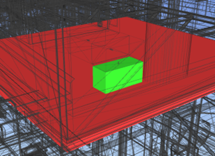
According to Figure 6, there is a conflict between a vertical air conditioning duct and a slab.
In this case, the solution to be implemented must be evaluated. The model can be corrected, or the current situation can be approved based on previously defined criteria.
Since the duct has significant dimensions, reducing the structural element where the duct passes may compromise the estimated quantity, so it is necessary to drill holes in the model.
Another consideration is that the structural element must accommodate slots at the design level, as it is necessary to design the required frames.
Therefore, we can organize the cases in such a manner:
a) Analyzed disciplines
b) Clashing elements;
c) Proposed solution;
d) Decision.
Situation 1 – Figure 6
a) Analyzed disciplines: Discipline a – Structures; Discipline b – Mechanical Systems
b) Clashing elements: Interference found: Slab x Air conditioning duct
c) Proposed solution: Drill holes in the model
d) Decision: The hole in the slab should be planned in advance to minimize the number of concrete structures required.
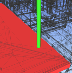
Situation 2 – Figure 7
a) Analyzed disciplines: Discipline a – Structures x Discipline b – hydrosanitary installations
b) Clashing elements: Beams x sewage network ducts – in cases where sewage elements are colliding transversely and/or without connections
c) Proposed solution: maintain interference
d) Decision: Small pipes will not significantly compromise the quantity of structures
Situation 3 – Figure 8
a) Analyzed disciplines: Discipline a – Structures x Discipline b – hydrosanitary installations
b) Clashing elements: beam x sewage pipe
c) Proposed solution: maintain interference
d) Decision: small pipes will not significantly compromise the quantity of structures.
Situation 4 – Figure 9
a) Analyzed disciplines: Discipline a – Structures x Discipline b – hydrosanitary installations
b) Clashing elements: Interference found : Beams x sewage network ducts – in cases where sewage elements are colliding transversely and/or without connections
c) Proposed solution: maintain interference
d) Decision: impact on the structural element, does not impact the quantities and the crossing position is in the center of the beam and was approved by the structural engineer.
It is also important to check whether the beam will be built in its entirety and then the slots will be made to pass the installations. In this case, the quantity of concrete and installations must be fully foreseen.
However, if the construction strategy is to predict the hole with waiting times, depending on the number of quantities of elements, it can be evaluated to drill the holes in the BIM model so as not to oversize the quantities
Situation 5 – Figure 10
a) Analyzed disciplines: Discipline a – Structures; Discipline b – Mechanical Systems
b) Clashing elements: Beams x sewer network ducts – in cases where sewer elements are colliding with connections
c) Proposed solution: fix the clash
d) Decision: impact on the structural element. Connections are occasional maintenance points and need to be accessible
Situation 6 – Figure 11
a) Analyzed disciplines: Discipline a – Structures; Discipline b – Mechanical Systems
b) Clashing elements: Beams x cold water installations vertically cutting the beam
c) Proposed solution: fix the clash
d) Decision: the standard positioning of the reinforcements conflicts with the element of the other discipline. There are possibly longitudinal (main) reinforcements that will be compromised.
Situation 7 – Figure 12
a) Analyzed disciplines: Discipline a – Structures; Discipline b – Hydrosanitary Systems
b) Clashing elements: Beams x ducts of sewage networks – in cases where sewage elements are clashing, not transversely.
c) Proposed solution: fix the clash
d) Decision: impact on the not bearing structural element. Passing pipes diagonally and not transversally can cause losses in relation to the execution and “life” of the elements.
Situation 8 – Figure 13
a) Analyzed disciplines: structures x electrical installations
b) Clashing elements: Beams x cable tray passing transversely to the beams
c) Proposed solution: Resolve the interference or predict the holes
d) Decision: depending on the standard dimensions of cable trays, it is recommended to foresee the slots so as not to overestimate the quantities of concrete structures
3. Conclusion
The appropriate use of Clash Matrices can give a lot of value when implemented in BIM models for various purposes throughout a project’s life cycle.
However, it is important to establish rules beforehand for approving and categorizing interferences. Currently, there are no references on this topic.
Therefore, it is crucial to start a discussion about it.
It is important to recognize that every project is different, and the rules to be followed must be discussed and defined together for each specific project.
These rules should be documented in the post-contract BIM Execution Plan before the project starts.

4. Bibliography
- BSI. PAS 1192-2:2013 Specification for information management for the capital & delivery phase of construction projects using BIM, London W4 4AL, British Standards Institution. 2013.
- BSI. BS 1192:2007, Collaborative production of architectural, engineering and construction information – Code of practice, London W4 4AL, British Standards Institution. 2007.
- BuildSMART. IFC Introduction. 2013 Available at: https://www.buildingsmart.org/about/what-is-openbim/ifc-introduction/accessed on April 20, 2019
- PENN STATE UNIVERSITY. BIM Project Execution Planning Guide. 3 Ed. Available at: https://www.bim.psu.edu/bim_pep_guide. Accessed on: April 2, 2021.
- REDING, A.; WILLIANS, J.; DAVIS, S. The New Zealand BIM Handbook: a guide to enabling BIM on built assets. 3 ed. New Zealand, 2019. Available at: Accessed on: April 2, 2021
- System Hierarchy and Clash matrix in BIM Coordination – BIM Corner – available at: https://bimcorner.com/system-hierarchy-and-clash-matrix-in-bim-coordination/
- H. Kulusjärvi, Common BIM Requirements 2012 – Series 6 Quality Assurance, buildingSMART Finland, 2012.


