
The Randselva Bridge is the world´s longest bridge built without drawings to date, as it is based solely on BIM models. It is a 634 m long cantilever concrete box girder bridge over the River Randselva in Norway, near the city of Hønefoss, around 50km northwest of the Norwegian capital Oslo.
In this article, you can read the first part of the series, where we write about the biggest challenges faced both by the design and construction teams. Moreover, we present the practical solutions which were used in this fascinating model-based project.
Table of contents
1. About the project
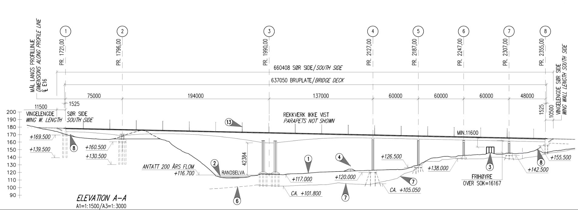
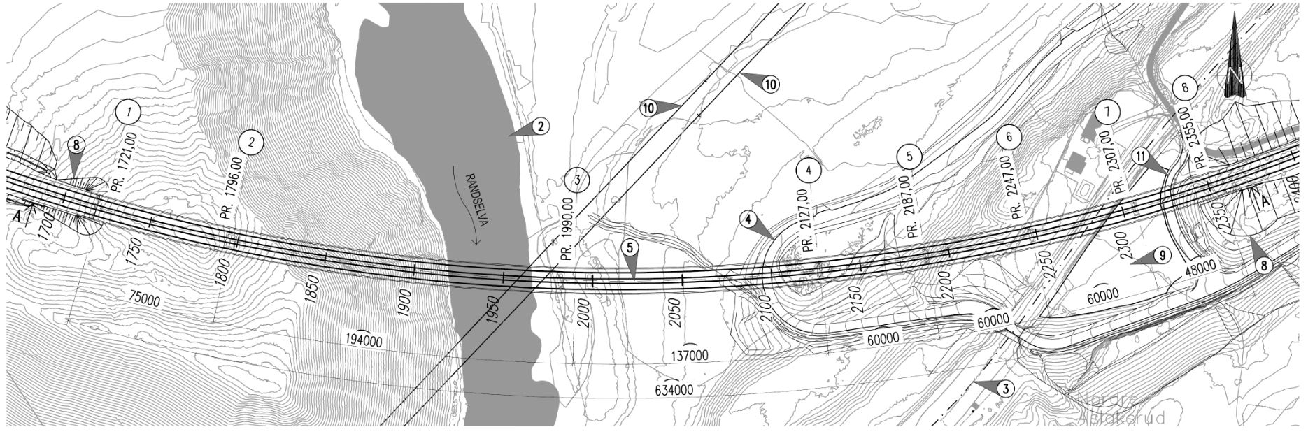
First, lets have a look at general project information. The Randselva Bridge (in Norwegian: Randselvabru) is a 634 m long cantilever concrete box girder bridge over the River Randselva in Norway, near the city of Hønefoss, around 50km northwest of the Norwegian capital Oslo. It is a part of the E16 highway, which goes through Norway into Sweden. The project comprised the bridge structure and 1,5 km of roads on both sides and opened in July 2022.
Contract type: Design & Build
Project owner: Statens Vegvesen (Norwegian Public Roads Administration)
Construction (main contractor): PNC Norway
Design, Calculations & BIM-models: Sweco Norway
Design, Calculations & Quality control of BIM model: Armando Rito Engenharia
Construction years: 2019-2022
Contract value: 463 million NOK (around 46 million Euro) ex VAT
The overall length of the bridge: 634 m
Four interesting facts:
- 95% of all information is transferred to contractor by IFC-files
- Parametric design has been used extensively
- The BIM-model contains over 200’000 rebars and 250 posttensioning cables
- Design team divided in 5 teams accross 5 countries (using Model Sharing)
2. Challenges for the design
Early in the tender phase, it was decided that the project will be conducted using BIM methodolgy, and that all the objects will be modeled in 3D. The bridge geometry is complicated, as it needed to fit to the existing terrain and the planned road. Therefore, the biggest challenges for the design were connected with creating a complex BIM model and included:
- Complicated geometry of the bridge
- A huge number of prestressed cables in the bridge deck
- Time-consuming modeling of reinforcement
- Handling of revisions
- Designers working in different countries
- Quality assurance of a BIM model
3. Solutions in the design
With each challenge, we can find a solution. On the Randselva bridge, we solved the challenges of designing a complex bridge without using drawings using following solutions:
- Dividing the project into parts
- Workflow
- Software
- BIM Execution Plan / BIM manual
- ICE sessions and hackathons
- Parametric design
- Correct information in the correct place
- Close cooperation with the contractor
- Visualisation of a model
In this first part of the serie, we will describe the first four solutions.
3.1. Dividing the project into parts
There is a famous saying: ‘How do you eat an elephant? One bite at a time!’. Or, in other words: cut the elephant into pieces. That means, dividing something big, which is difficult to handle, into smaller parts, which are more manageable. A similar method can be used when approaching a difficult or complicated project. On the Randselva Bridge, because of its size, early in the project it was decided to divide the models into 8 substructure parts for every single axis and 3 superstructure parts.
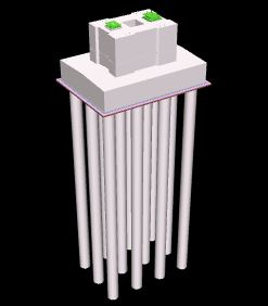
What is most important, is to divide the structure into practical construction parts, according to the production method of the contractor. This is why, for instance, the substructure had 8 independent models. For each axis from 1-8, the model comprised piles, foundation, and column. In that way, the working team from the contractor could open just the relevant model that they needed for the production.
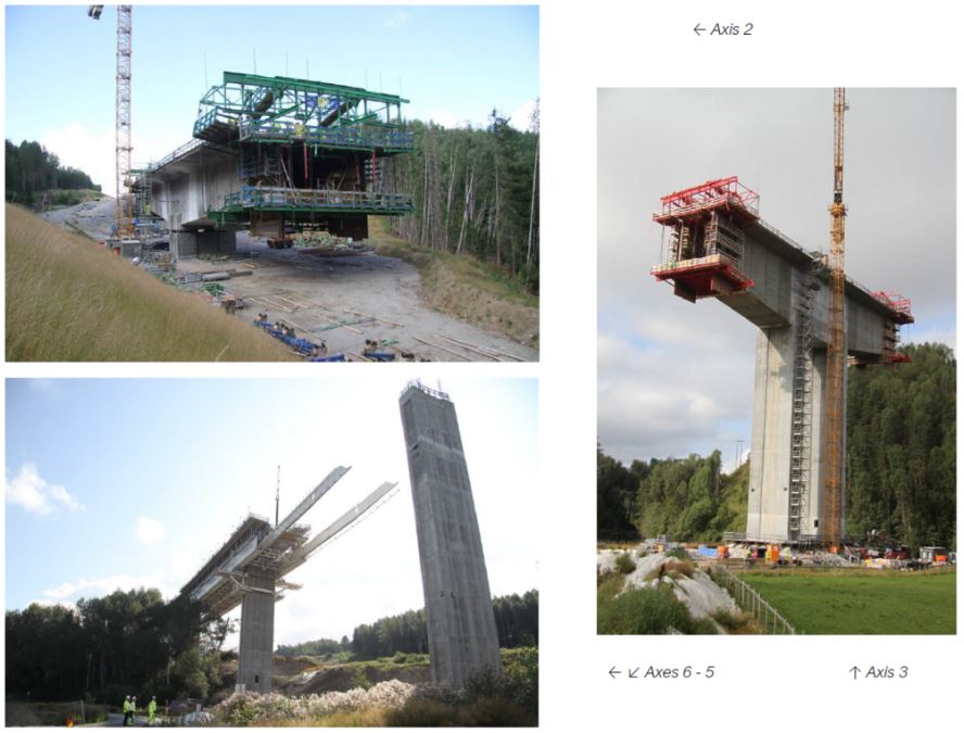
In the tender phase of the project, because of the time schedule, the contractor decided to start building the superstructure in three places: on axis 2 (free cantilever method), on axis 3 (also free cantilever method), and on axis 8 (moveable scaffolding system, or MSS). For that, three sets of equipment were employed. As a result, the designer divided the superstructure into 3 parts:
- From axis 1 to axis 2,5 – Free cantilever method
- From axis 2,5 to axis 4 – Free cantilever method
- From axis 4 to axis 8 – Moveable scaffolding system
Another advantage of dividing the project into parts are smaller models (with less file size), which could be opened and managed more quickly. However, there is also a challenge connected with these divisions: the design team needs to remember the interface between the models. For example, the starting reinforcing bars that are in the superstructure, need to be modeled in the columns, since they will be executed in the first place. The designers should make quality control by merging the models together and checking if the interfaces between the parts are taken care of.
3.2. Workflow
A key to successful use of BIM is understanding who will use the BIM-model and understanding what kind of information the users will need to withdraw from the model. The Randselva bridge BIM-models are being used for multiple purposes along its way from design to operational state, as illustrated in the BIM workflow in the figure below. Users of the multiple stages will normally have different information requirements and use different software to extract the data.
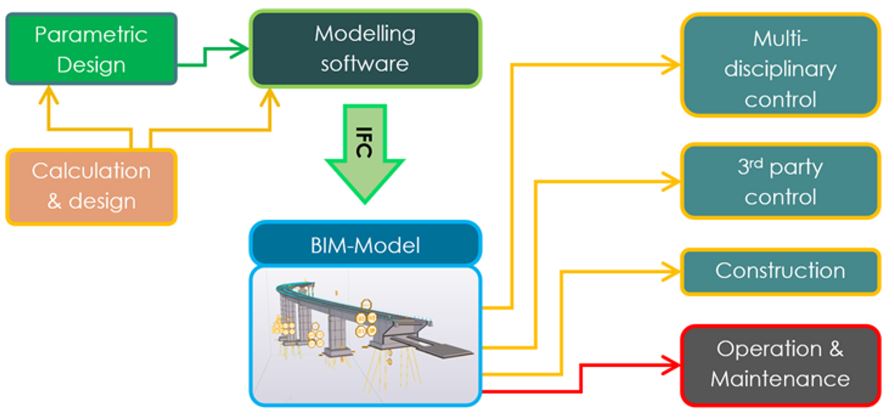
On the Randselva bridge project, multi-disciplinary control and 3rd party control are mainly done by using Solibri in combination with BCF-files.
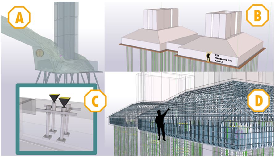
At the construction stage, the model was being used for the following four main purposes schematically shown in the figure below:
A. Earthworks and backfilling
B. Constructing scaffolding / Surveying
C. Producing and placement of third-party products
D. Installing reinforcement (and post-tensioning)
These four different purposes all need specialized software and work methods.
3.3. Software
Choosing an optimal level of details in a BIM-model is very important. Objects need to be modelled with enough details to be useful in clash control and understanding scope of work. At the same time, too many details will make model very large and software will start lagging and be difficult to control.
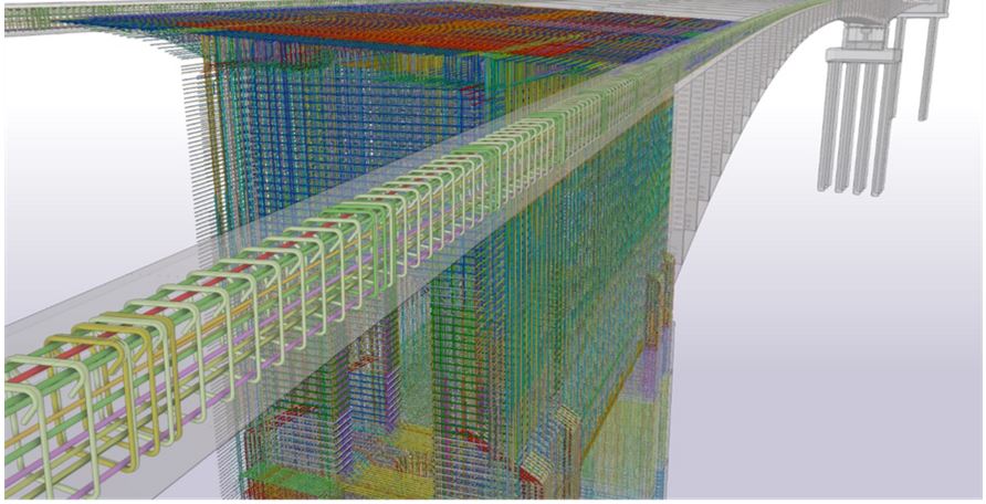
Post tensioning tendons and anchorages are important components in the Randselva bridge and are the reason why the slender design is possible. Due to the bridge curvature in plan view and the combination of two different structural systems, the post tensioning geometry is very complex, and the position of the components is not flexible. However, only the outer shape of the tendons geometry and anchorages is important to model correctly, as it will form the basis for clash control.

The steel strands and the inner geometry of the anchorages are taken care of by the company delivering the product and does not need to be modelled. An excerpt of the 200 tendons modelled at Randselva bridge is shown in the figure above.
In addition to the tendons, all structural reinforcement needed for the Randselva bridge project has been modelled. This gives a very good understanding of which clashes must specially be designed and fitted due to clashes and potential installation problems. All rebars in the BIM-model are however not clash free. A pragmatic approach is chosen where some clashes between rebars in the model are accepted as long as it is obvious that clashes can easily be adjusted at construction site. This has been thoroughly agreed with PNC Norge AS, the company responsible for the bridge works.
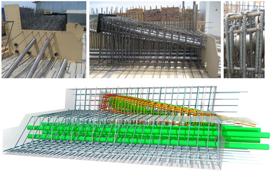
Another advantage of modelling all rebars is that reinforcement can be ordered directly from the BIM-model, eliminating the need for manually made bar bending schedules. In areas with heavy reinforcement and limited space like blisters for post tensioning anchorages, many projects traditionally produce 1:1 mock-ups at worksite to test constructability. For the Randselva bridge project, these mock-ups have been produced digitally and have proven to be a very efficient and cost-effective way of engineering.
In particular, due to the bridge curvature each blister position and corresponding reinforcement are almost unique. In the BIM-model, local adjustments on the general and blisters reinforcement were made for every blister. This would traditionally require a great amount of specific drawings to avoid extra work at site. A comparison between a mock-up assembled at worksite and a digital mock-up developed for Randselva bridge is presented in the figure below.
3.4. BIM Execution Plan / BIM manual
BIM Execution Plan (BEP) or the BIM manual, as it is more commonly known in Norway, is a central document describing the level and objectives of BIM use on the project, dividing responsibilities, and presenting workflows. It was an important document on a model-based project such as the Randselva Bridge.
The BEP consists of two parts: a general and a project-specific. The general section applies to all BIM projects in a company and it describes work processes and areas of use for BIM. The project-specific part is filled in after contracting the designer in the BIM-start-up meeting. It defines the project-specific framework for data flow, interdisciplinary planning, and collaboration in the project.
The BIM manual is a living document that should be continuously revised in the project, if necessary.
The purpose of BIM Execution Plan / BIM manual is to ensure common expectations, good interaction and understanding between all stakeholders in the project. The BEP should describe how the company carries out BIM projects with a model as the central information carrier from the early stages to planning and production. The document provides a description of the requirements for BIM collaboration in the project, and how responsibilities, execution and participation in the activities must be taken care of with a focus on model management and the end product – the BIM model used for execution, and, if agreed on with the client, during the facility management (FM).
For the Randselva Bridge, the BIM manual was prepared together by the contractor and the designer, after a series of meetings. The document was updated during the project, when new methods or workflows were found to function better for this particular project.
Key content in the BIM Execution Plan / BIM manual:
💡 Common agreement in the project about its BIM level and objectives. These will have consequences on the modeling and structure of the model
💡 Clarification and setup for roles, responsibilities, interaction, and interdisciplinary control. Usually clarified during a start-up meeting
💡 Main information, as project layout with units, 0-point, and coordinates, project and model division, and naming
💡 Simple modeling principles, information about software and file exchange
Summary of first part
In this first part of the series about the world´s longest bridge built without drawings, we had a look at the general project information, challenges for the design, and 4 of the solutions to those challenges. Stay tuned for the next part, where we will cover the rest of the solutions for the design:
- ICE sessions and hackathons
- Parametric design
- Correct information in the correct place
- Close cooperation with the contractor
Bibliography
In the creation of this series and the case study, we have used the following sources:
- RANDSELVA BRIDGE: PLANNING AND BUILDING A 634m LONG BRIDGE SOLELY BASED ON BIM MODELS Øystein Ulvestad, Sweco Norge AS Tiago Vieira, Armando Rito Engenharia SA
- RANDSELVA BRIDGE: CONSTRUCTION WITHOUT DRAWINGS Wiktor Rybus, BIM Developer, Sweco Norway (until 01/2022 PORR/PNC)
- https://e-brim.com/randselva-bridge-digital-twins-bim-in-south-korea/
- https://www.ringeriksavisa.no/arkiv/item/8429-randselva-bru-apner-uten-budsjettsprekk
- Authors of some of the photographs: Ståle Savland (SVV), Konrad Naborczyk (BIM Corner/Skanska
- Renderings: SWECO