
To implement BIM successfully into a project, it’s simply necessary to have some kind of plan and BIM process describing the way of doing it. In the BIM world, this plan is called BIM Execution Plan, in short, BEP. This series of articles is designed to help the reader become familiar with this document and to be able to create it themselves, adapting it to their own needs.
In the first two parts of the series, I talked about what BEP is and why it’s so important. We defined specific implementation goals and determined the areas where we will use BIM to achieve these goals:
PART 1 – What is BEP ? Why is it important? Defining BIM goals for the project
PART 2 – BIM Uses
Today, however, we will address another important topic bringing us closer to creating a fully-fledged BEP, namely: Creating implementation processes. Does it sound serious and confusing? If so, don’t worry, I’ll just lay it on the line. After reading this article, you will certainly be able to create your own BIM implementation processes and understand its components better. Here we go.
The following article is included in the "How to become BIM Coordinator" In case it’s the first post you came across, I encourage you to read the introduction of the full series. I explain there how the articles have been organized to make sure you can get the most out of the series. Have a good read.
Table of Content
INTRODUCTION
In the previous article (part 2), we identified the areas where we will use BIM for a sample hospital project, remember? (If not, please see point 4 of the previous article).
We selected 3 main BIM uses. These were 3D Modeling (read also: Design authoring), 3D multidisciplinary coordination, and Construction works analysis (BIM 4D)

Now it’s necessary to demonstrate to the project team the ways of using the abovementioned applications during the project implementation. To do this, you will need to create processes, specifically process maps. These will provide the project team with clearly defined, graphically documented procedures that they need to follow to put a specific BIM application into practice
The so-called BPMN (Business Process Model and Notation) standard will help us create the maps. I recommend several tools that will simplify map creation and make it less time-consuming:
- Lucidchart – https://www.lucidchart.com/
- Gliffy – https://www.gliffy.com/
- Microsoft Visio – https://www.microsoft.com/pl-pl/microsoft-365/visio/flowchart-software
Firstly we need to divide maps maps into two levels:
At level 1, we prepare a BIM Overview map showing the relationships between the different BIM uses throughout the project lifecycle. At level 2, we create detailed process maps for each of the BIM Use. In our case, we will create:
Level 1: A general BIM overview map for the entire project
Level 2: Detailed process maps for the three BIM uses:
- Design authoring – 3D modeling
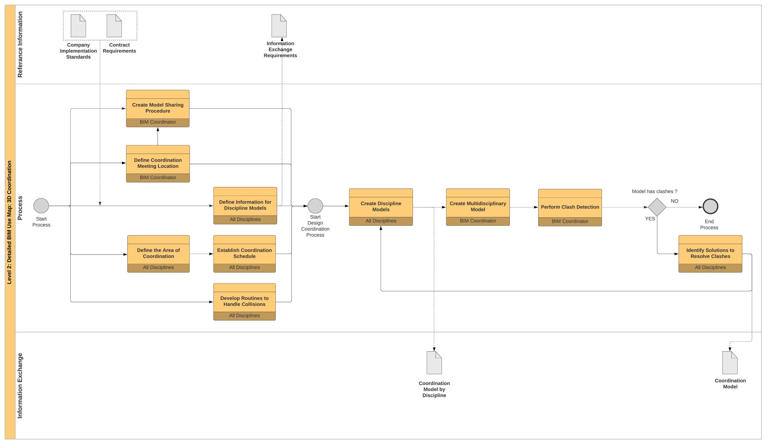
- 3D multidisciplinary coordination
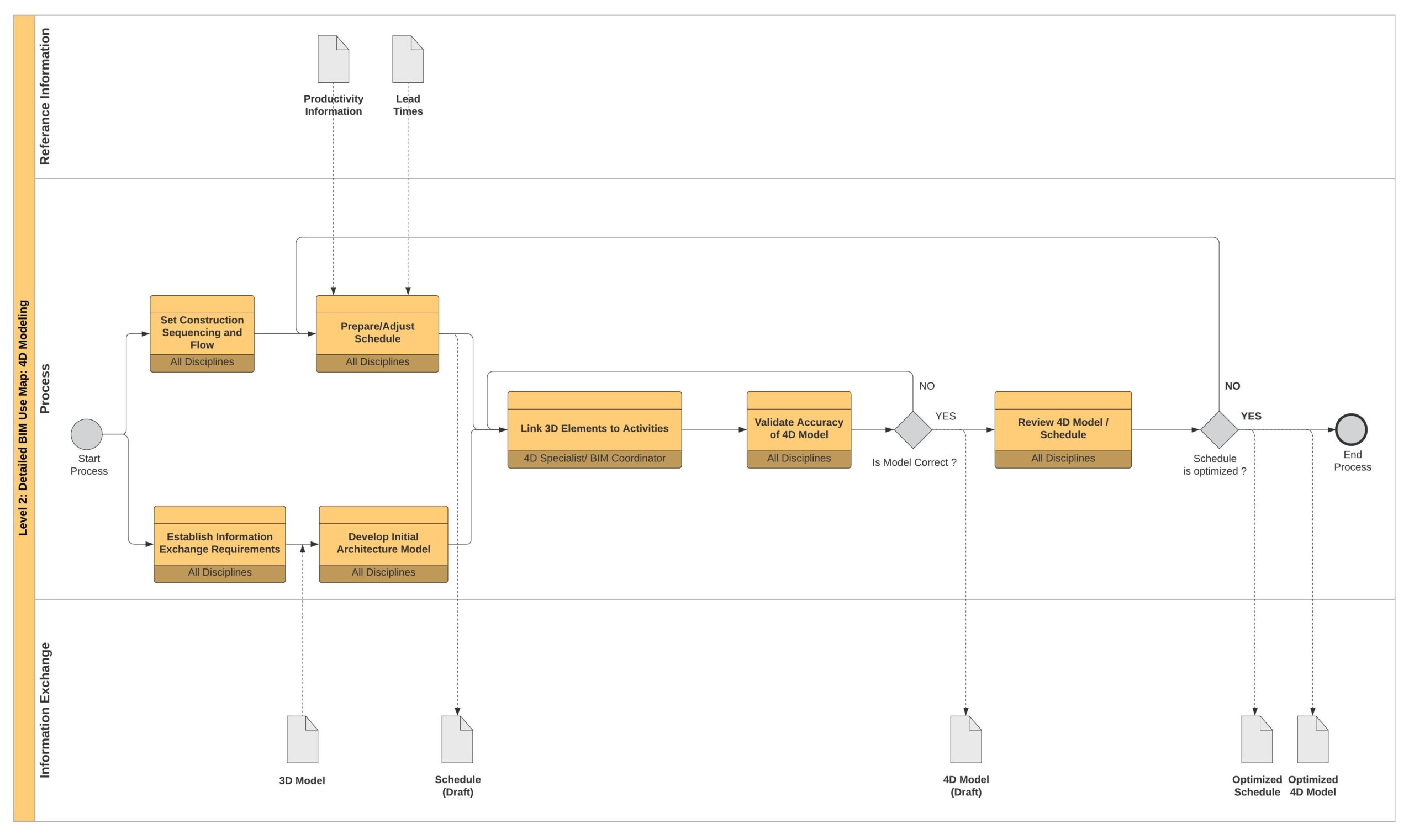
- Construction works analysis
In total 4 maps.
CREATING A GENERAL MAP OF THE BIM PROCESS
The general process map is a bird’s eye view of our BIM implementation plan. It contains all of our selected BIM applications. It also illustrates the ways of exchanging information between the models we use throughout the project lifecycle.
Okay, let’s get to the specific steps and create such a map.
STEP 1
First, we need to start by putting potential BIM applications on our map. Each one will be illustrated as a process in the following manner.
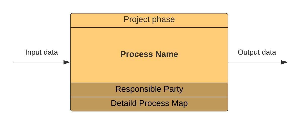
- The arrow on the left side symbolizes the data needed to initiate a process. For example: If the process is a 4D simulation – the necessary input data will be a previously created 3D model on which the simulation can be performed.
- In the middle of the rectangle, we place the name of a given process, and above, we indicate in which phase of the project, a given process will be carried out.
- Below the name, we provide information regarding who is responsible for a given process. It’s worth considering more deeply who will be the best choice on the project. Occasionally, there can be several responsible parties for one process. The selected discipline is supposed to determine exactly what information is needed to carry out a given process and what information from a given process will “come out”.
- We also provide a link to a detailed map of the particular process, giving a detailed illustration of what happens in such a process.
STEP 2
The next step involves arranging the processes logically and chronologically according to the project phases and documentation delivery requirements.
For example, we won’t arrange the processes so that we will first carry out inter-industry 3D coordination and then create models because that wouldn’t be possible. The logical and chronological approach consists of creating models first and then coordinating them.
STEP 3
The final step involves determining the information that will be exchanged between the processes and project parties. We illustrate which documents or models on the map will appear in the process or will be the result of the process.

For example, we will use the above graphics and two processes. The result of the process “Creation of design models” is an architectural model, a construction model, and HVAC model (letter A). These models will be required for the next process “3D Coordination”. In addition to the previously mentioned models, subcontractor models will be involved in the process: Plumbing model and Sprinklers model (letter B). Note that the arrow comes from the middle of the process (letter C), not from the right side (letter D). It means that the models will be involved in the process, but they won’t be the result. The final product will be a coordinated model (letter E – note that the arrow comes out from the right side of the process).
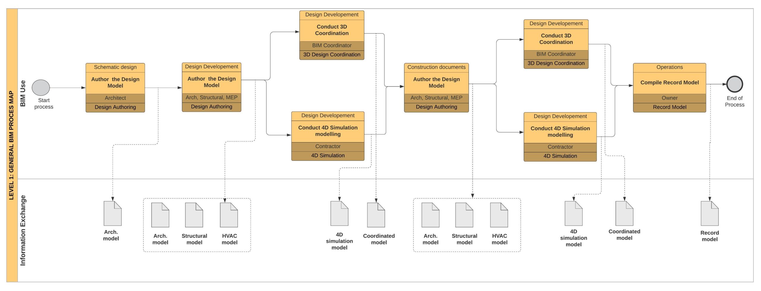
As you can see, these 3 simple steps allow you to create process maps for even the most complex engineering projects. Below you will find a general process map of a sample hospital project that we discussed in the previous two parts of the series. In this example, we will arrange 3 BIM Uses (Desing Authoring, 3D Coordination, 4D Construction Analysis) in different project phases.
CREATING A DETAILED BIM PROCESS MAP
Once a BIM overview map of the processes occurring in the course of the project has been created, detailed maps for specific BIM use should be performed.
There are many ways to create a specific process map, and it all depends on the company, project, technical solutions, and organizational structure. There is no golden mean or strict rule in this case.
When creating a detailed map, we must consider our specific situation, adjust the process, and adapt it to the nature of the project.
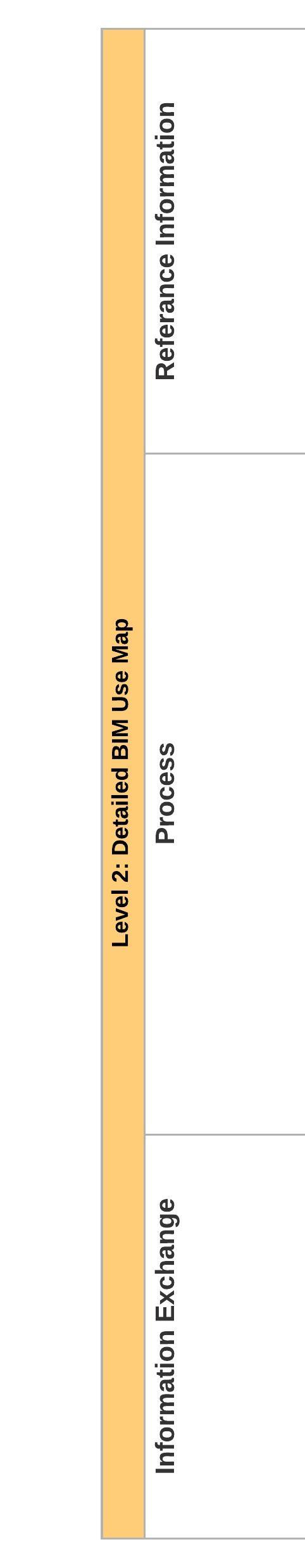
First of all, please note that the detailed BIM process map includes three categories of information, which are shown on the left side of the process map. The components are placed in horizontal lines (called “lanes” in the BPMN mapping notation). These categories include:
- Reference information: structured information resources deriving from external or internal sources that are required for the proper execution of the process.
- Process: a logical sequence of activities constituting a specific BIM use.
- Information exchange: BIM products from one process that may be required as a resource for future processes.
STEPS TO CREATE A DETAILED MAP OF BIM USE
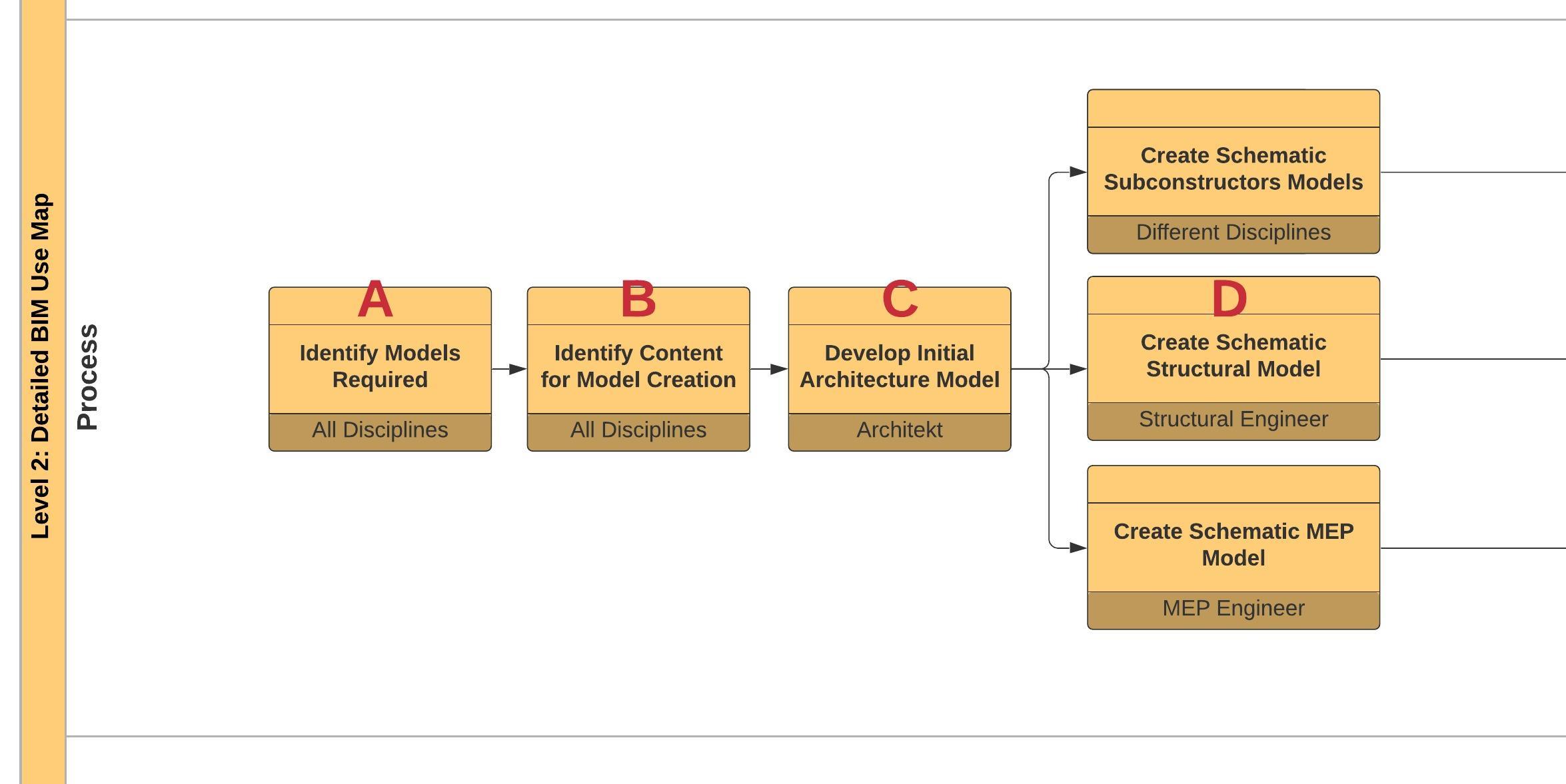
Step 1: Distribute BIM uses into simple processes and arrange them in chronological order.
As process maps creators, we need to identify the main processes that occur during the delivery of a given BIM application. Then we must arrange these processes in a sequence of their occurrence in the project delivery cycle.
For example, we will use BIM to create 3D documentation in our project:
Letter A: First, we have to think about the models we will need. Will they be just architectural models, or perhaps also models of other industries? Therefore, the first process is to “Identify Models Required”.
Letter B: Then we need to determine what elements we want to create in the models. What information we add and to what extent we detail the model components. Thus, the next process is “Identify Content for Model Creation”.
Letter C: Then the creation of a schematic (preliminary) architectural model begins
Letter D: Based on the initial model from the architect, other discipline models are created
As you can see, we arranged the main processes in chronological order providing a logical whole.
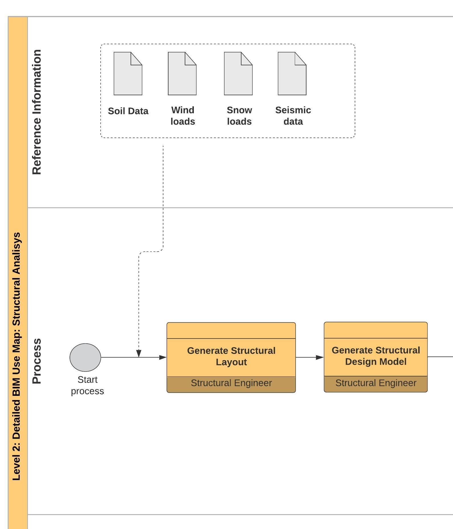
Step 2: Add supporting information to the map.
- Add refernece information to the map.
It’s extremely important to add reference information to our maps. It provides us with data required to get the process done properly.
For example, in the following case, we create a process map for the application of the BIM “Structural Analysis”. To carry out such an analysis and create an analytical model of the structure, external data (reference information) such as wind, snow, or seismic loads, etc. are required. (Letter A).
Similarly to general process maps, here again, we must demonstrate the way we exchange information between processes. More about it – (see step 3 of the general process map)
- Add Responsilbe party
The last element is to add the information which party of the project is responsible for a given process. It gives us confidence that each group involved in the development of the project will have clearly defined roles and tasks to perform. We created a similar indication of the responsible party on the general map. (Step 1.c)
Step 3: Add decision gateways to the process
The decision gateway is nothing more than a point in the process where verification whether the intended goal has been achieved occurs. It allows us to create iterative loops, create branches in the process, and control whether the received data meets the required criteria. Decision gateways are marked in BPMN notation as a rotated square. Below you can see an example of using a gateway:
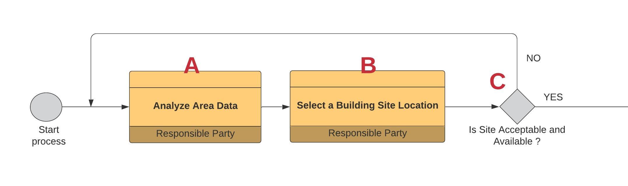
Letter A: Above, we see a part of the process illustrating the use of BIM for the analysis of the site. Initially, there is the first process “Analyze area data”,
Letter B: After that, we choose the optimal place where we would like to implement our investment,
Letter C: Then, we come to the verification gateway, where we have to check whether the place we choose is available, whether it’s allowed to build in this place, and if it meets the conditions of the ordering party. If so, we move on to the next processes, if not, we go back to point 1 and start looking for a new area for our project.
Since we already know how to create detailed process maps, let’s get to our 3 BIM uses, which we mentioned earlier, namely: Design Authoring (creating 3D models), 3D Multidisciplinary Coordination and 4D Construction work analysis
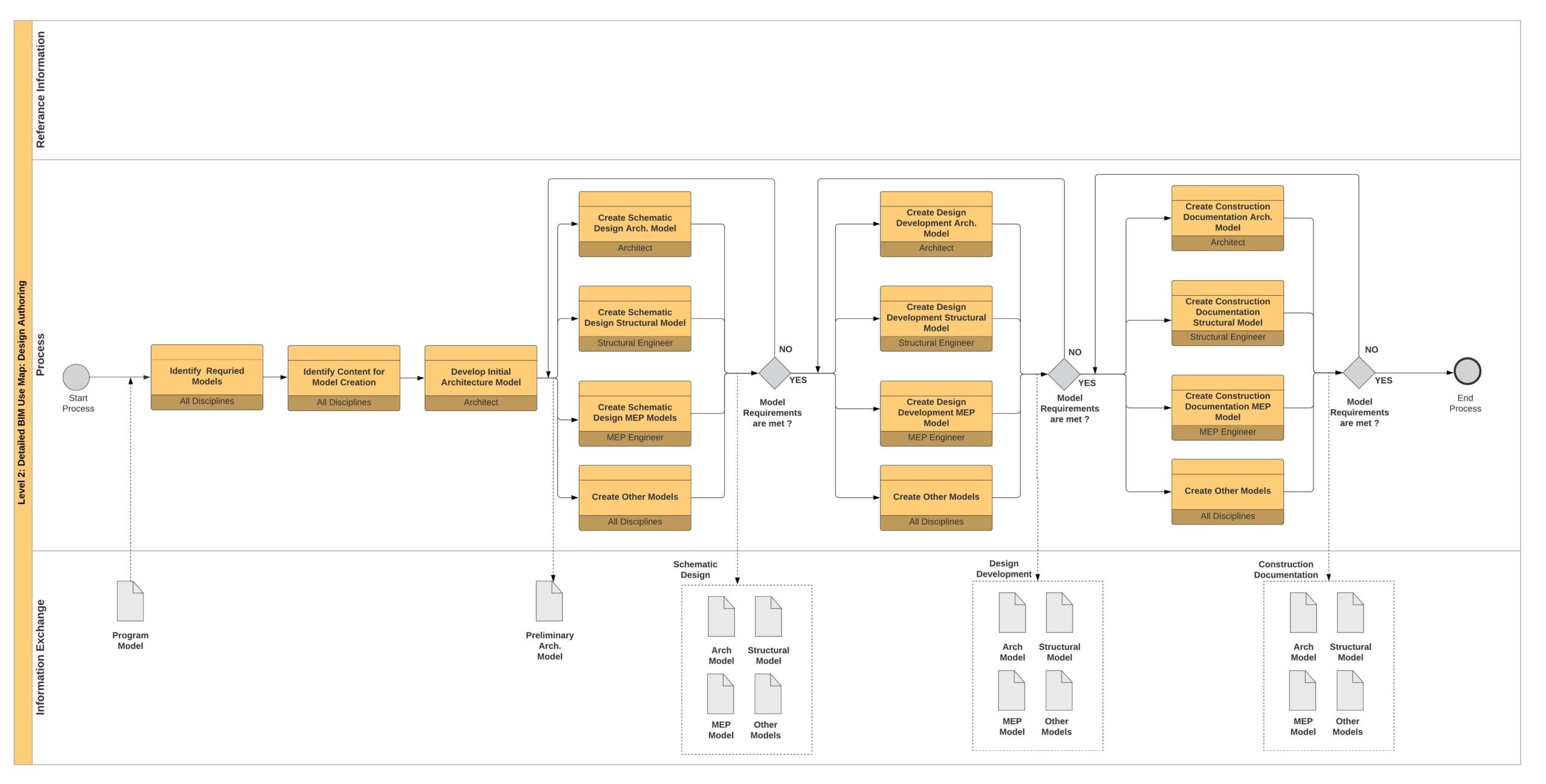
Remember that detailed maps can be used for other projects that will also want to implement a given BIM use. It’s good practice to update maps regularly by checking that the theoretical sketches are reflected in reality. Otherwise, it’s worth introducing changes to the process, which reflect the actual state of the given implementation more accurately. Additionally, after the project is completed, it may be helpful to review the process maps to compare the actually used process with the planned one.
SUMMARY
Today we discovered an effective tool to plan the implementation of BIM into our project. Creating process maps will help us to organize the way we want to carry out the implementation “in our heads”. The visual aspect of maps provides project teams reading BEP a better understanding of how the implementation will look like. It’s often said that “one good drawing is worth 1,000 words”, in the case of maps, this statement is absolutely relevant
I wonder what you, dear reader, think about this way of documenting and planning work with BIM. Does BEP also have similar practices on your project? Please feel free to write your comments and remarks in the section below. In the next article of the series, we will approach the issue of information exchange on your project in detail. Thanks for being with us. See you in the next post.
The information contained in the guide is based on my own experience but also inspired by Penn State University’s work in the BEP development:
https://www.bim.psu.edu/
as well as ISO 19650-1 and 19650-2 standards:
https://www.bsigroup.com/en-GB/iso-19650-BIM/
Check out other articles from about Creating Successful BEP:


I’m just starting to plan a Bim Manual an want to understand BEP and implementation processes, this article is really useful! didn’t know about this kind of flowchart, definetly gonna give it a try to plan implementation at the office! cheers!