

Would you like to learn more about BIM COORDINATION? JOIN AN ONLINE PROGRAM TO BOOST YOUR SKILLS
When working on projects that use the BIM methodology, problems often arise with the amount and quality of information that is added to 3D models. More than once I have dealt with situations where carefully modeled windows, doors or beams landed in the trash, because the architects changed their minds regarding design.
In such a situation, was it the fault of the architects that they changed the previous design conception? Or maybe the fault of engineers who created the model in too much detail at such an early stage of the project ?
It’s hard to give an unambiguous answer here, but I am sure that the cause of the above-mentioned problem is a poor planning of the information exchange throughtout project lifecycle.
When creating a BIM Execution Plan, it is important to create guidelines specifying which elements of the model, at specific level of detail, should be modeled and delivered to other project participants. Thanks to such planning, we will avoid the situation of creating too detailed or too poor in information BIM models thus efficiently controlling the quantity and quality of the created data.
The following article is included in the "How to become BIM Coordinator" In case it’s the first post you came across, I encourage you to read the introduction of the full series. I explain there how the articles have been organized to make sure you can get the most out of the series. Have a good read.
One step back ....
To create a proper information exchange plan we should first look at general map of BIM processes, which we designed in the previous article (check BEP – Part 3).
We created one of these maps for fictional project of the Oslo hospital ward (picture below):
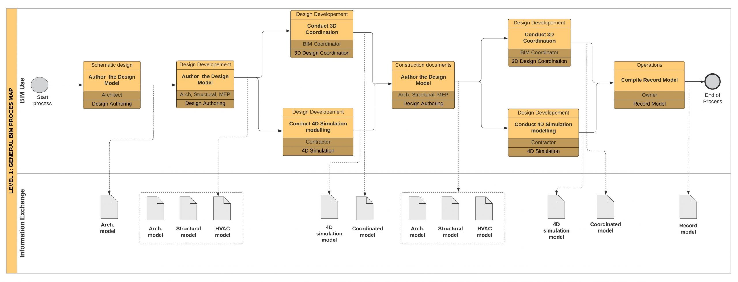
The map consists of two lanes. First shows different BIM Use processes arranged in chronological order. The second one represents the ways information exchanges between processes. Our task is to precisely define what information and model elements will be exchanged between given processes.
Information Exchanges between BIM processes
Let’s look at a part of the process map and focus on one information exchange. In the figure below, we can see 3 BIM application processes:
A – Design Authoring B: 3D Coordination, C – 4D Simulation.
Information is exchanged between these processes in the form of an Architectural, Structural and HVAC models. The authors of the models are respectively architects, structural engineers and HVAC engineers, while the recipients are the general contractor and BIM coordinator.
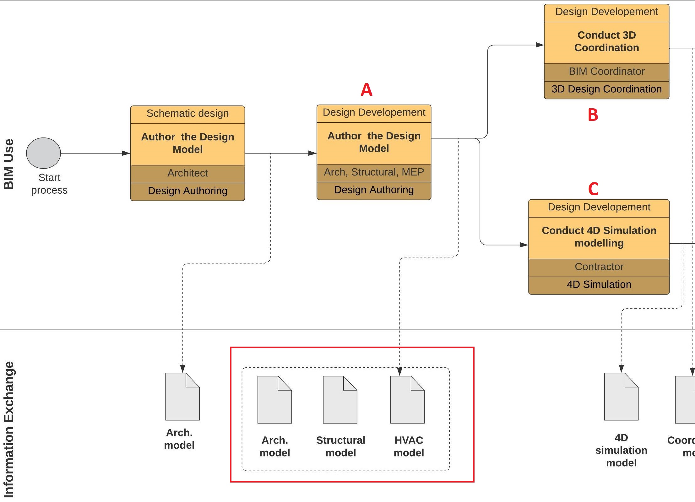
The models created during the design authoring process will later be used to perform multidisciplinary 3D coordination and to create a 4D simulation.
If the models do not contain the elements needed for the next process, the missing information must be created by the party responsible for the BIM Use.
In these cases, the project team decides who should author this information and determines when to include it in the BIM process.
Below I will present the procedure for creating requirements sheet for information exchange. Using it, team members, and in particular the author and recipient of each information exchange transaction, will know exactly the content of the exchanged model elements.
Steps to create an information exchange worksheet
To create an information exchange work sheet you should follow 5 steps:
STEP 1: Identify potencial information exchanges using BIM overview process map.
We have already done this in the previous paragraph. We took a closer look at the general map of BIM Use processes and selected a specific place where the information exchange takes place.
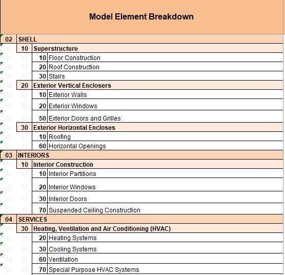
STEP 2: Choose Model Element Breakdown structure that fits to your project
We need to use some classification of building elements. Using it, we will select those model elements that are included in the information exchange. It is worth using the existing, popular classifications such as Uniformat II or OmniClass.
STEP 3: Define Requriements for each Information Exchange
a. Define the recipient of the information exchange. E.g. structural engineer, general contractor etc.
b. Determine data exchange format and version which will be used during the exchange. E.g. IFC 2×3 file or the Revit 2019 format (.rvt)?
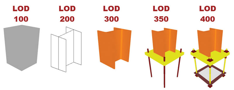
c. Set the level of detail of exchanged information. Here, we can use our own classification previously agreed with team members or use existing classifications.
I especially recommend the LOD Level Of Development classification created by BIM Forum – you can find detailed specification about it here – (LOD specification)
d. Sometimes it will be necessary to add additional comments that will specify more precisely the requirements for the model content.
STEP 4. Determine the responsible party for creating the required information.
It is recommended to use discipline shortcuts to make a worksheet more readable and easy to use. E.g: A – Architects, STR – Structural Engineers, C – contractor etc.
STEP 5. Compare created model content with the recipient’s model requirements.
After adding all mentionedabove data to our worksheet, the project team should review the document in order to find any information requirements discrepancies.
There may be situations when the model recipient has higher information requirements than received in an authored model.
In such cases, appropriate countermeasures should be taken. We have two options:
1. The author can add the required information to the model so that it meets the recipients’ requirements – the so-called verification of information.
2. The recipient of the model will take over the responsibility for adding additional information necessary to carry out the BIM Use process – the so-called responsible party verification.
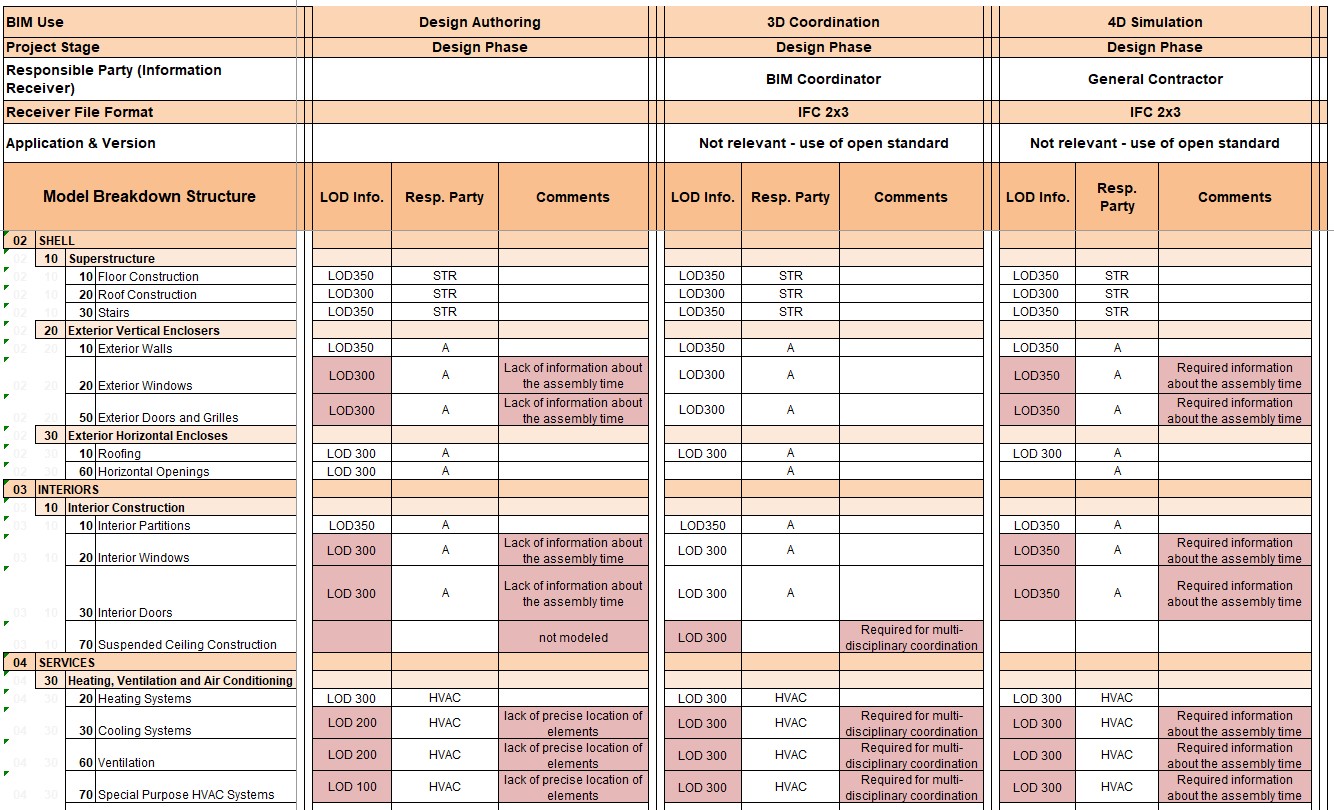
Below we see an example of an information exchange sheet created for the previously considered case. It uses the Uniformat II classification. To simplify the example, only a few elements of the classification have been selected.
During the Design Authoring process, architectural, structural and HVAC models were created. After that, content of this process is delivered to subsequent processes, ie 3D Coordination and 4D Simulation.
Pay attention to the places marked in red. This is where the discrepancies appear between what the authors of the models (Architects, Structural engineers, HVAC engineers) have created and what the recipients required (BIM Coordinator, General Contractor).
Let's sum up
Today we learned how to define information exchanges throughout the various project phases. Thanks to them, we will have control over what and when have to be modeled. I hope this article gave you basic knowledge about infromation exchanges and will help you build your Successful BIM Execution Plan. Good luck with planning 🙂
The information contained in the guide is based on my own experience but also inspired by Penn State University’s work in the BEP development:
https://www.bim.psu.edu/
as well as ISO 19650-1 and 19650-2 standards:
https://www.bsigroup.com/en-GB/iso-19650-BIM/
Check out other articles from about Creating Successful BEP:


“Here, we can use our own classification previously agreed with team members or use existing classifications.”
It would be interesting how to start develop our own classification.