1. What is Model View Definition (MVD)?
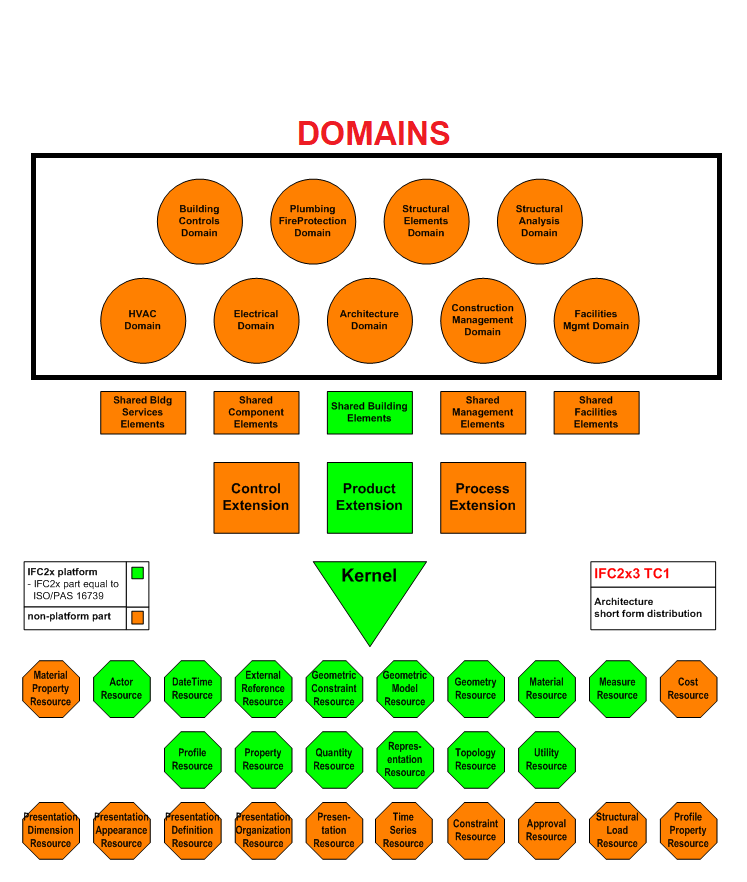
The IFC schema structure is modular and includes elements for specific domains, such as Architecture, Structural Analysis, Electrical Installation, etc.
IFC aims to create an interface among various tools to exchange information. However, not each program has an internal data schema that stores all specific classes in each domain. Let us remind that there are about 12000 of them.
Think, for example, of Tekla Structures modeling software. It doesn’t include data about the humidifier (IfcHumidifierType) or the occupant (IfcOccupant). Such information may be useful for creating a simulation of the building’s climate and energy balance or evacuation simulation, thus it isn’t included in the program.
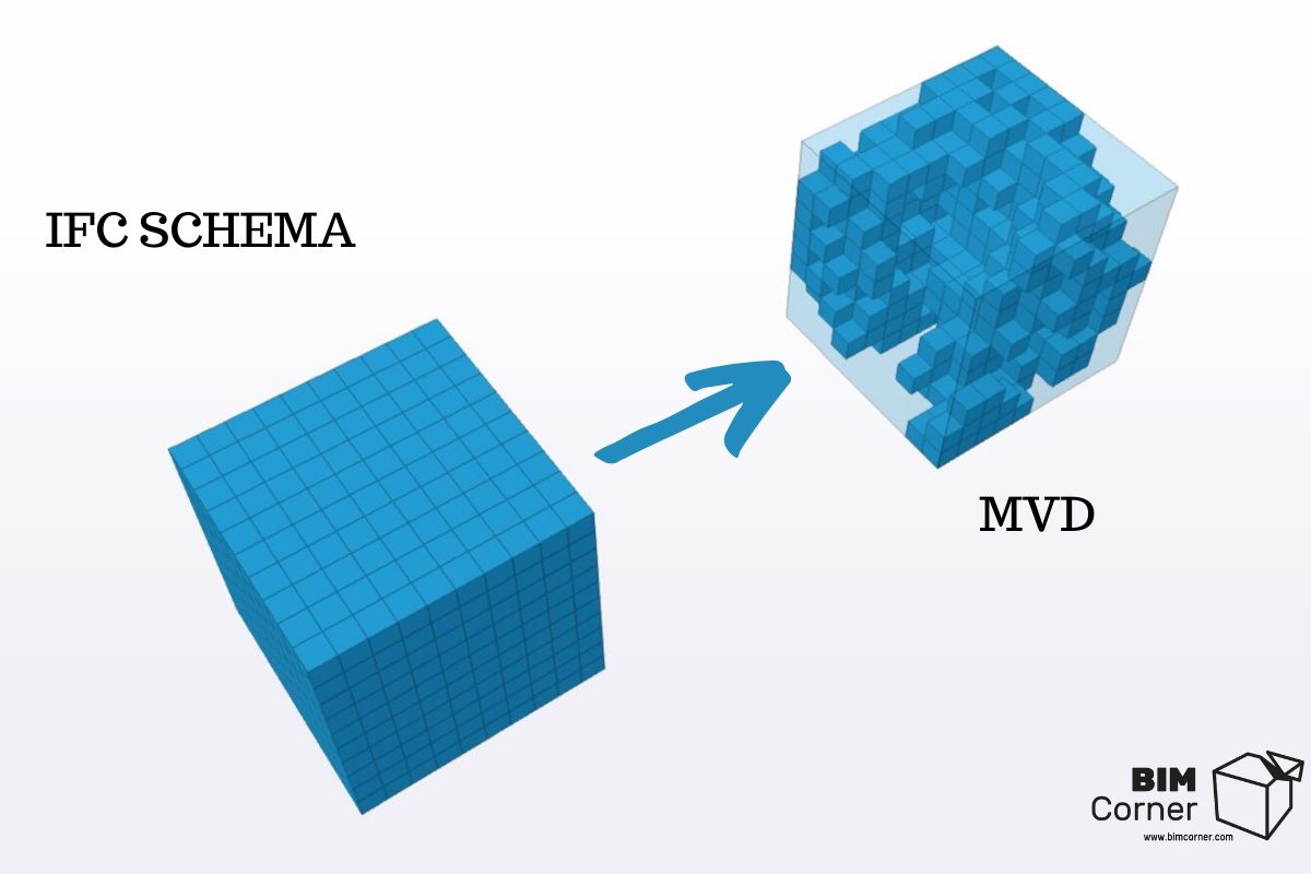
It should, therefore, be clarified which subset of all IFC schema data is needed during the exchange for a specific application. In other words, which information needs to be filtered from the entire IFC schema.
Such subsets of data can be defined by analyzing the general schema of IFC in smaller “packages”, namely the MVD. They define the user requirements for necessary information. The MVD describes which objects, representations, relationships, concepts, and attributes are necessary for the project participant and the application to perform the requested task.
The Model View Definition also specifies which part of the IFC schema is implemented by a given program.
The developers of each software can choose the list of IFC classes, which support IFC import and export features. It means they can create their own Model View Definitions.
It’s important to realize that in fact, every IFC export feature in every program is based on the MVD.
2. Examples of MVD
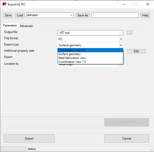
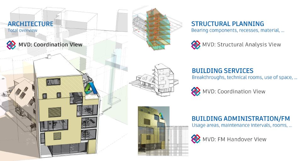
The most common type of MVD for IFC version 2×3 is the Coordination View. The Coordination View is a filtered version of the full IFC schema. It’s also created to coordinate the project among multiple users and disciplines in the project. Eventually, it’s one of the main IFC applications in BIM technology.
Official buildingSmart MVD’s for IFC 2×3
-
Coordination View – spatial and physical elements for design coordination among the architectural, structural, and installation sectors (MEP).
-
Space Boundary – identification and export of additional space boundaries (polygons defining the extent of space contact with directly adjacent surfaces (such as walls, floors, ceilings) and openings). It can be used for building energy analysis and Quantity take-off.Basic FM Handover View – a basic view providing data for facility management (Facility MAnagement). Transfer of model information to CAFM (Computer Aided Facility Management) and CMMS (Computerized maintenance management system) applications. The basic scope of the view can be summarized as a list of spaces and equipment for spatial and technical object systems. This view corresponds to the following requirements of the abovementioned Coordination View:the ability to assign items of equipment and furnishings to rooms,assigning rooms to zonesassigning a classification to spaces and components,assigning the basic manufacturer’s properties to the components (standard and non-standard IFC properties),assigning doors and windows to space,assigning component type information (IFC product type)exporting basic quantities for all project components and spatial structures
- One example is the COBie, a specification used to provide information on facility management. It’s a spreadsheet data format to provide a subset of building model information, not geometric model information.
Structural Analysis View – a structural analysis model, developed in a structural design program, sent to one or more structural analysis programs.buildingSmart officially defined two MVDs for IFC4
-
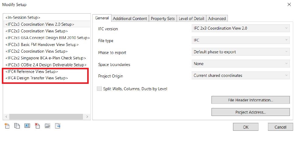
Reference View – a simplified geometric and relational representation of the spatial and physical elements of the reference model, to coordinate the project among different industries – architectural, structural, and installation (MEP).
-
Design Transfer View – an advanced geometric and relational representation of spatial and physical elements to enable the transfer of model information from one tool to another. It’s not a two-way transfer, but a higher level of unidirectional data transfer and responsibility. It’s applied when the model exported from one program (for example, architectural) is the starting point in another program, where the model is converted to native objects and continues to work in that program.
You can find the official versions of Model View Definitions (MVD) here:
https://technical.buildingsmart.org/standards/ifc/mvd/mvd-database/
Other examples of MVD
-
Architectural Design to Structural Design – where the architect provides the structural engineer with a model “background” which can be referred to when arranging and designing the structural elements.
-
Architectural Design to Quantity Takeoff – where the architect provides the general contractor with a model with the exact location of the elements to extract quantities and allocate cost figures.Building design analysis for energy analysis – where the architect or designer/engineer introduces a model to the energy engineer with specific construction types and thermal values of materials, along with thermal comfort values for indoor spaces to determine the building’s performance.
The Coordination View is also a subset of IFC, used for official certification of software by buildingSmart. What does it mean in practice?
BuildingSmart certification for programs involves the import and export of IFC according to the model view definition and not the full IFC schema. Software providers can also define their own subset or filter, namely their own MVD. They can develop MVDs to exchange data necessary for energy or evacuation simulations. In this case, it will be preferable to include such an MVD containing, for instance, an occupant class ifcOccupant (essential for creating an object evacuation simulation).
3. Who operates the MVD?
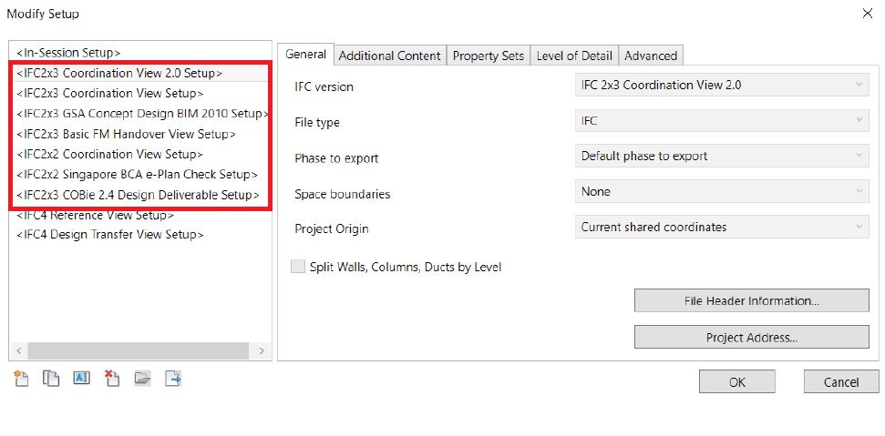
All applications supporting BIM data export via IFC have some MVD support. In general, the tool for creating BIM includes a list of MVD options.
You can find list of all software certified by buildingSmart here: https://www.buildingsmart.org/compliance/software-certification/certified-software/
4. Summary
What should you remember from the above text?
It’s important to realize that in fact, any IFC export feature in any program is created based on the Model View Definition. No program uses the entire schema but only filtered parts of it when exporting to IFC.
Software providers can develop their MVDs inside their programs depending on the needs and purpose of the program, which is an essential and flexible use of the IFC schema.
As a user, you should remember that when discussing data exchange through IFC, you are actually talking about Model View Definition.
Did you like that post ? Share it with others !
We spend a lot of time and effort creating all of our articles and guides. It would be great if you could take a moment to share this post !
Share:
Comments:







Important information by simple words. many thanks!