
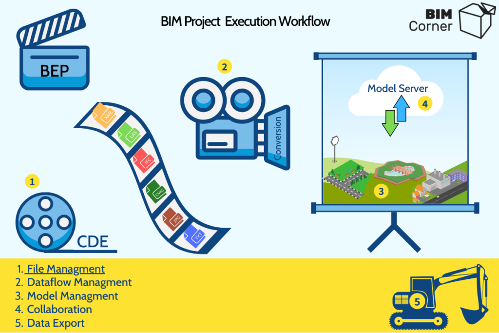
In the previous article on BIM Corner, I described the activities required from a BIM Coordinator in the initial project phase. Let us mention that the culmination of the initial phase lies in creating BEP (BIM Execution Plan), which is a digitally editable document, usually in PDF format. We can describe all of the procedures and routines occurring in the project in such a document. Information including model naming, data exchange, folder structure, etc. are available there. It’s modified throughout the project. Also, the methods, practices, and procedures are constantly updated.
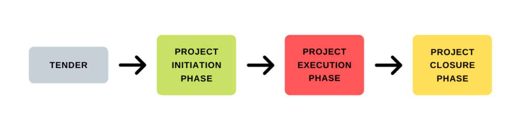
Following the project’s chronology, let’s skip to the next phase, namely the Project Execution phase.
For the better understanding of whole phase I devided it into 5 processes:
- File Managment
- Dataflow Managment
- Model Managment
- Collaboration
- Data Export
Each process requires individual discussion due to its characteristics. In the following article, I focus on the role of files in the BIM world.
Table of Contents
BIM Formats
If you look at the digital BIM world, you’ll realize there are many file formats, either open or closed. The Open File refers to a file format you can open and process in any BIM software. Whereas, the Closed File is a native file, assigned to a particular program. While importing it into other software, it’s possible to lose some of the stored data. Furthermore, it’s difficult to identify the correct purpose of individual files or what information each file may contain. For example, certain files are suitable to export lines and points, while others are suitable for 3D planes and solid. Some contain existing objects when others include designed models.
Having analyzed the topic for a long time, I feel like the correct cognition and use of files according to their purpose is one of the foundations of BIM at the highest level. Therefore, we’ll have a look at the role and purpose of file formats available in infrastructure projects supported by BIM technology.
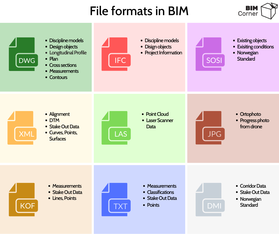
A major advantage of this format is its versatility. Typically it saves geometry of discipline models and designed objects with information coded in the layer name. Also, it frequently serves as digital documentation. It may include design objects such as longitudinal profile, development plan, or cross-sections. It’s used as a foundation for designing the geometry of infrastructural structures, i.e. road, railway, sewage system. And finally, it may contain GIS data, an orthophoto map, objects describing an existing situation, measurements, as well as contour plan.
Format created by buildingSMART. It’s usually used in a 2×3 format . It includes discipline models and designed objects. Note that it may contain a large amount of non-geometric information. It’s used in non-drawing projects. It’s possible to download information from an IFC file for calculating material quantities. Finally, the IFC file provides information applied in the building maintenance phase.
A Norwegian standard. Also mentioned in the article: BIM IN INFRASTRUCTURE… LET’S START FROM THE BEGINNING – BIM OBJECTS. It contains data on existing conditions (GIS). The SOSI format features standardized structure classifying objects. It divides objects into categories following Norwegian standards. Each object has a unique code and name.
A format mainly for infrastructure objects. This format describes planes, curves, and points. Also, it enables recording information regarding the cant and design speed. It’s operated by machine control systems.
A format designed for recording point clouds derived from laser scanning. Its size is often large, up to several GB.
When it comes to the world of infrastructure, it’s essential to have high-quality pictures taken from drone strikes, reflecting the existing situation, i.e. orthophoto maps. These are usually saved in JPG format. Images may also reflect the progress of construction works.
A format used for measurements. It contains data regarding the name, point, and line. For example, it may contain information on the location of vertical signs or measurements of curb position.
A format used for measurements. This format is used to save COGO points. The TXT format is also applied to many other points, such as the input file in the Quadri object classification tool. (We’ll discuss it in more detail in the subsequent part of the articles)
Standardized Norwegian format. It provides transport corridor data. The file format allows the receiver (contractor) to further processing the model. The model isn’t ‘dead’ and locked as in the DWG file. It’s useful when, for example, the exposed rock layer is different from the rock that was assumed based on measurements during the design. The contractor can edit the 3D model to obtain correct calculations of earth masses. Format is supported by machine control systems.
Levels and types of information
So, we learned the main files supporting the BIM Coordinator in their work. The next element is the type of information contained in the files. For this purpose, I selected the most popular formats. These include IFC, DWG, and LandXML. Let’s compare them with Quadri (MMS – Model Management System, adapted for the infrastructure industry).
Each of the above formats has a similar information structure, divided into 3 levels* (in the DWG file we distinguish 2 levels). Based on such a division, we may assume the following:
- level 0 – object,
- level 1 – attribute,
- level 2 – property,
- level 3 – information.
Each format is capable of recording geometric and non-geometric information. The geometric information contains typical attributes describing elements such as:
- Curve,
- Volume,
- Surface,
- Point.
The amount of non-geometric information depends on the file format. Therefore, let’s take a look at the information carried by the 3 most frequently applied files in the infrastructure industry.
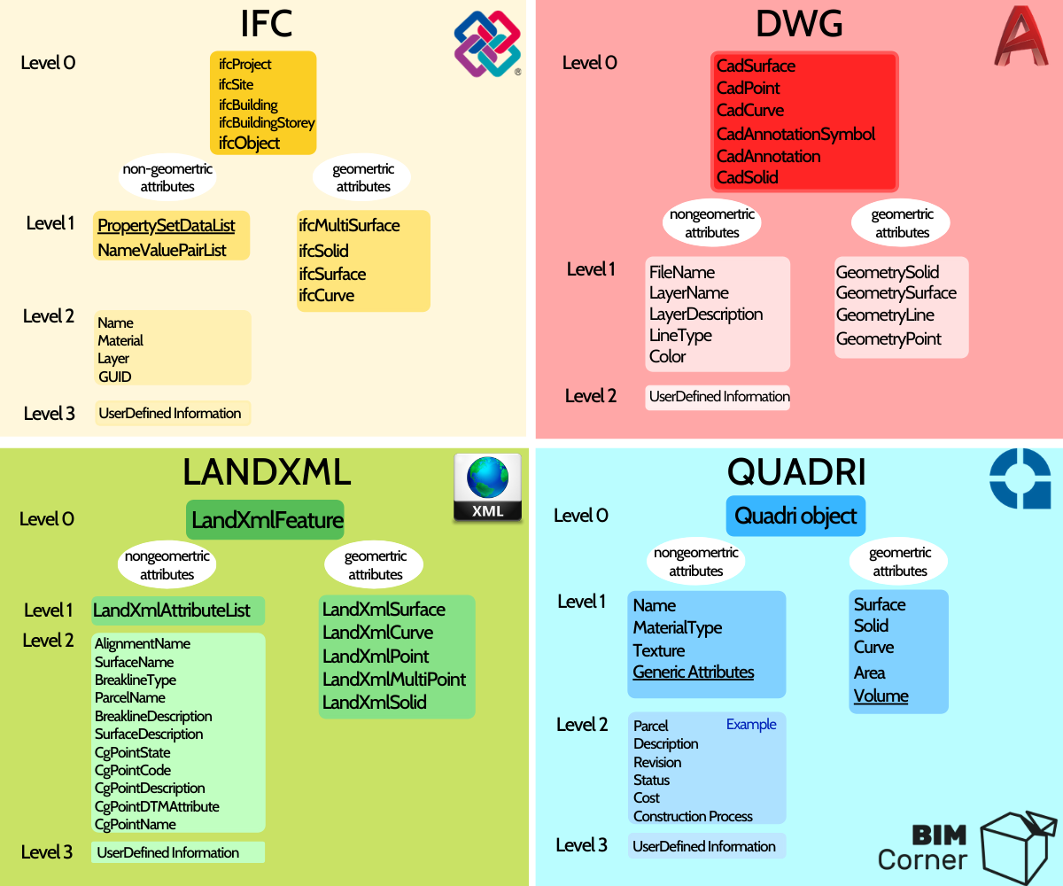
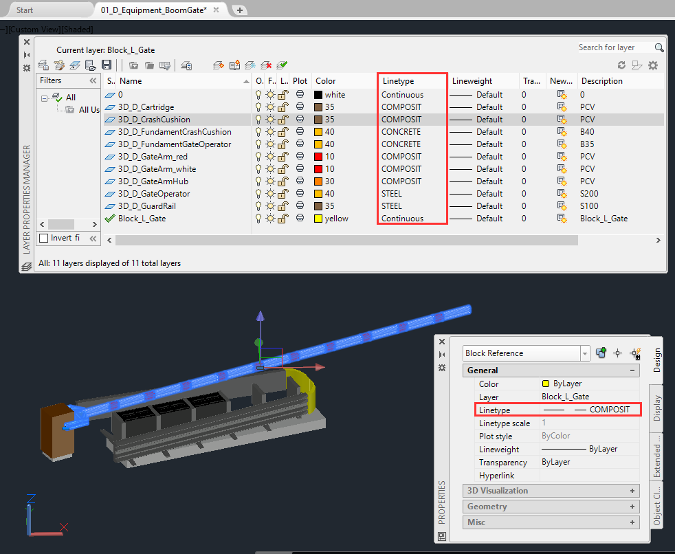
DWG – The DWG file is capable of recording non-geometric information directly on attributes, level 1. These are the following attributes:
- Filename,
- Layer name,
- Layer description,
- Linetype,
- Color,
It's a common practice to code design information into layer names. Typically, such descriptions contain information concerning the type of object, material, texture. For example: 00_D_fundament_concrete_B40_t-concrete. The information can also be encoded in the attribute responsible for the Linetype. Description of the Linetype is presented with e.g. ByLayer, Dashed, Continous, Dashdoted. AutoCAD provides the possibility of composing own Linetype. Therefore it is possible to encode additional information hidden under the lines Name. The information is visible in a further edition of the DWG file. Such information may be, for instance, LOD,LOI,MMI, material, etc.
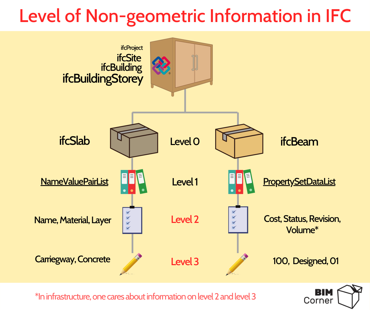
IFC – The IFC file transfers the largest amount of non-geometric information of all the listed files. It’s divided into 3 levels. At level 0 you find an object called ifcObject along with higher structures. IfcProject is comparable to the Block used in AutoCad. It has general information such as the name of the project, the type of software in which the file was created. The key information describing the individual project objects are saved at the lowest level. The IFC gives you the possibility to store information under the attributes NameValuePairList, responsible for saving information regarding Name, Material, Layer Name, or GUID. The PropertySetDataList attribute allows assigning more information characterizing the project. The information can be found here in the form of Textsting.
LandXML – LandXML file in its current version has 3 levels of information. There is no extension of the features number. The replacement of the above file is the GML file. At level 2 we may find information such as routing line name, surface name, or surface description.
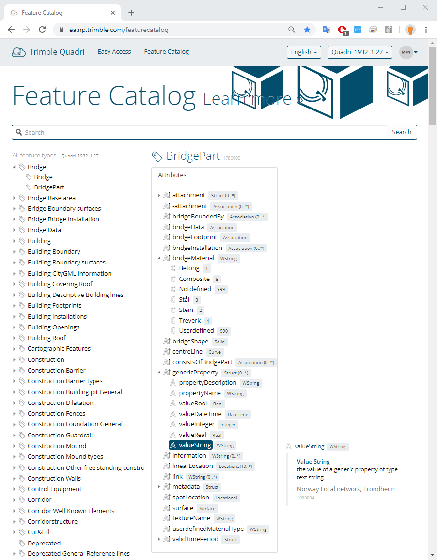
QuadriModel – is an example of a native format opened in a 3D visual model management program. The program features its object library in the infrastructure. According to Feature Catalogue the catalog contains similar categories as the SOSI file. Each object (level 0) has an attribute (level 1) and possibly a feature (level 2). The equivalent of the PropertySetDataList from IFC is genericProperty in Quadri (it helps to save the information at level 3).
Information in the IFC File
The IFC file, due to its structure, allows encoding of information on several levels. It’s assumed that the IFC file is adapted to transfer information found in cubature construction. However, it’s only partly true. IFC in its current form is successfully used in infrastructure construction. This is because the information on levels 2 and 3 can be easily extracted while omitting the division into object types (IfcSlab, ifcBeam, ifcWall, etc).
Currently, several tools have been developed to filter the information contained in the IFC file. In the E39 project Kristiansand – Mandal, in which I participate, all discipline models are delivered as IFC files. Then these files are placed in the program, allowing object-oriented visualization of the multidisciplinary model. The ISY Projekt tool supports the storage and display of the multidisciplinary model in the mentioned project. The program has been created specifically for the project to allow browsing without drawing documentation for the project. Among its great functionality, it’s possible to display only necessary information describing the model. For instance, if you click on any object in an industry model, the program displays only the information at levels 2 and 3, thus omitting the IFC file structure.
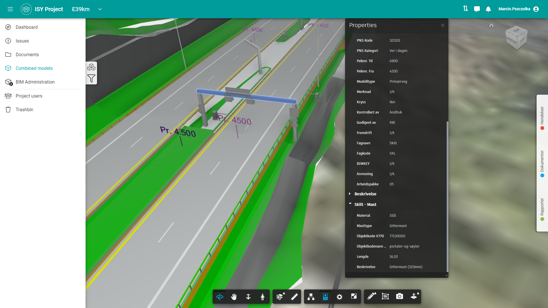
An example of non-geometric information in the IFC file is the information in the table of the drawing paper documentation. It may also be information describing the parameters appearing in the construction detail drawings. This may include information such as:
- Layer volume (e.g. 200m3),
- Length (e.g. 16m),
- Material type (e.g. Concrete C30),
- Layer name (Frost Protection Layer),
- Designer (Marcin Pszczolka),
- Controller (Krzysztof Wojslaw),
- Cost per 1m3 of material (300 PLN),
- Status (MMI 300).
IFC for infrastructure and reason why I'm not waiting for it?
I hope I convinced you of the importance of knowing the types of files and their purpose. Remember the knowledge of the information sharing system is a solid basis for arranging conversion files. This I will write about next time. It’s a key element determining whether all data created in the BIM digital world will be used properly.
Finally, I can also add, I’m not waiting for IFC for the infrastructure. I believe the new version of the IFC file will only make it easier to describe the data, but won’t be a salvation to the infrastructure industry as many people think. The IFC file in its current form is sufficient. It has the right geometry and attributes to assign a lot of non-geometric information. With a programming language such as Python, or tools such as ISY Project or BIM Sync, you can easily extract data from level 2 and 3 and analyze them in programs such as Power BI.


Great content! Super high-quality! Keep it up! 🙂
Thanks! We will!
nice article. remember gml is also a bim format.
Thank you very much! 🙂
Really interesting! Thanks.
Regarding data for surveyors, IFC 4.1 (and further) will fix that issue, correct geometry is important here too