With each challenge, we can find a solution. On the Randselva Bridge, the project team solved the challenges of designing a complex bridge without using drawings using many different solutions.
In this second article, you can read about the other four practical solutions that were used in this fascinating model-based project: ICE sessions and hackathons, parametric design, correct information in the correct place and the close cooperation with the contractor.
Table of contents
1. About the project (first part)
2. Challenges for the design (first part)
3. Solutions in the design (first part)
3.1. Dividing the project into parts (first part)
3.2. Workflow (first part)
3.3. Software (first part)
3.4. BIM Execution Plan / BIM manual (first part)
3.5. ICE sessions and hackathons
3.7. Correct information in the correct place
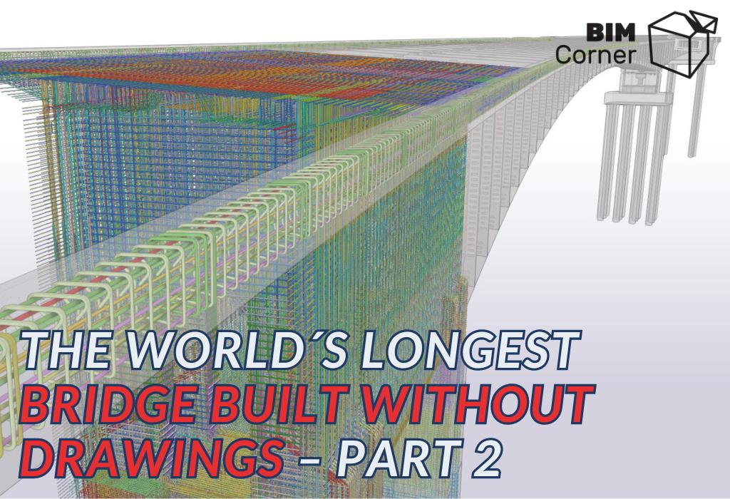
This is the second part of the series about Randselvabru – the world´s longest bridge built without drawings. In the first part (read here), we had a look at the general project information, challenges for the design, and 4 of the solutions to those challenges. In this second part we will cover the rest of the solutions for the design:
- ICE sessions and hackathons
- Parametric design
- Correct information in the correct place
- Close cooperation with the contractor
3.5. ICE sessions and hackathons
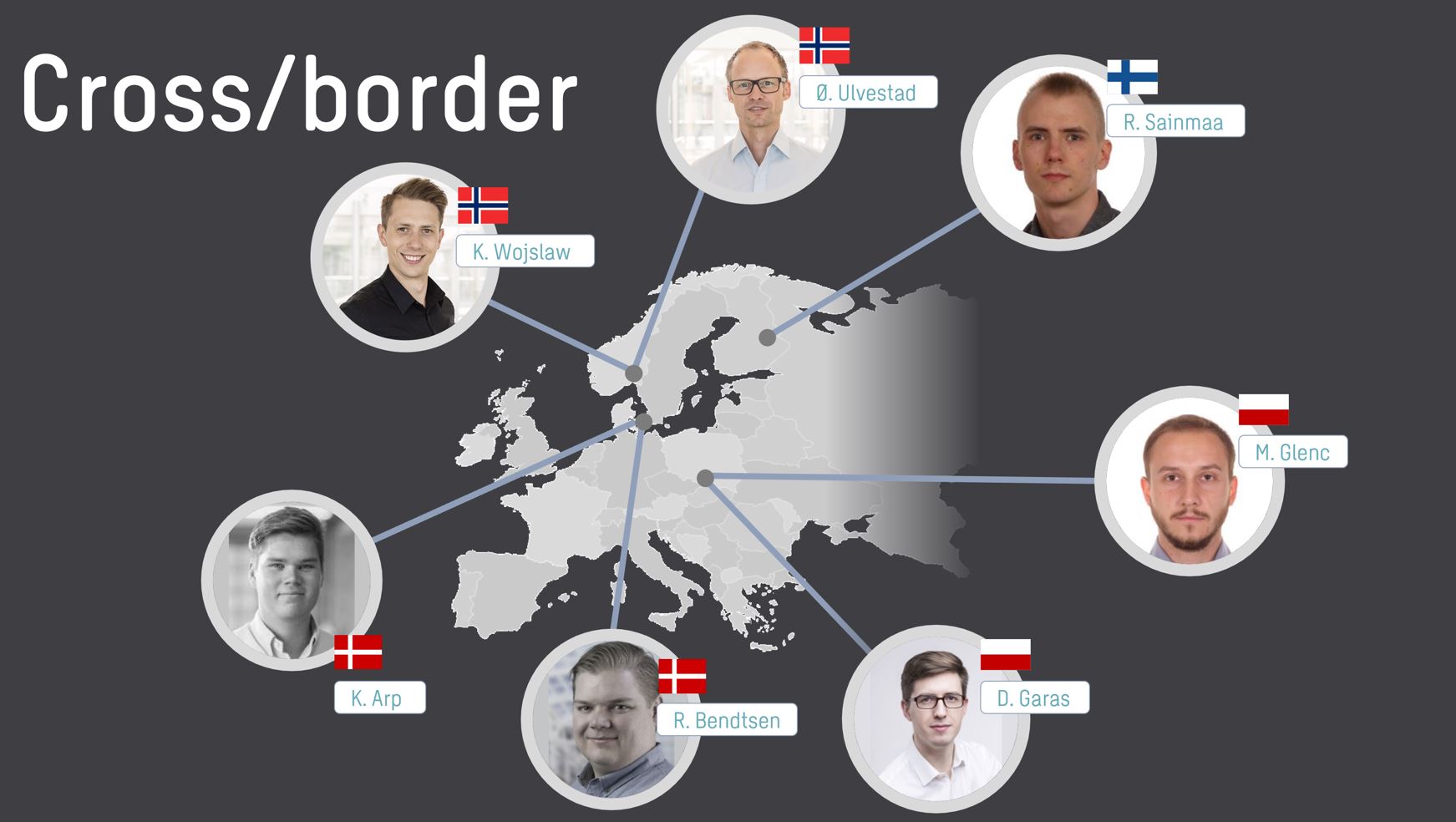
Crossborder Parametric Team
Local design teams in four countries were modelling the bridge, using Tekla Structures together with Grasshopper. Early on in the design-process the team aimed at creating at least 70% of the BIM model using parametric design. The design office knew that only five to six people in Sweco knew parametric design at this extremely high level, and only one of them was located in Norway. As the rest were located in Finland, Denmark, and Poland, instead of an expensive relocation to Oslo, the designers created a workflow where the teams would be able to work with cloud-based models from their local offices.
An advantage for cross-border cooperation: A BIM model looks the same in any country, while drawings are very country-specific. Thus, cross-country collaboration becomes easier.
ICE Sessions
On the Randselva project, the team applied the VDC methodology. One of the elements in the VDC framework is Integrated Concurrent Engineering. ICE is a meticulously planned multidisciplinary meeting, with simultaneous design work. You can read more about the VDC here.
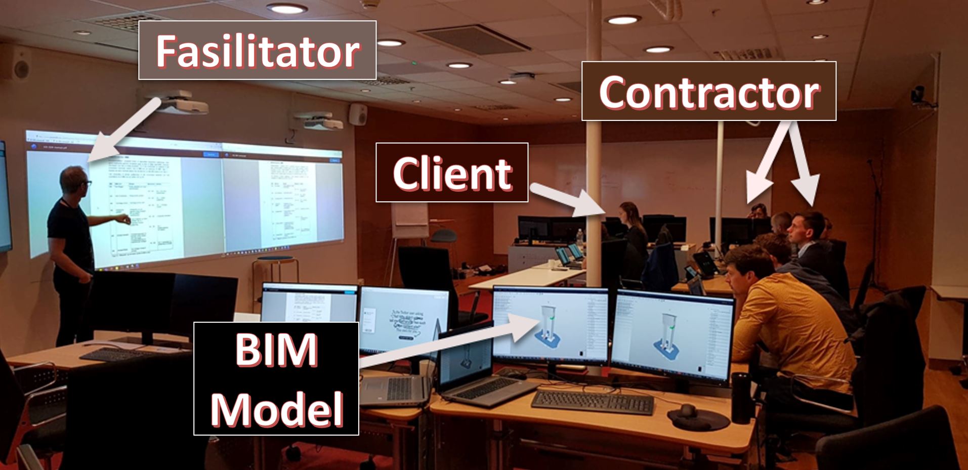
The use of ICE aims at solving design challenges. Significant decisions concerning the project were made in real-time. Meetings were organized with the latest visualization technologies in specifically designed rooms, known as Big Rooms. The participants used projectors and large touch screens displaying BIM models. Based on such models, the participants analyzed problems and discussed solutions. Additionally, the meeting plan and agenda were supervised by the so-called facilitator – a person responsible for the smooth course of the meeting, implementing a predefined program down to a minute.
On this project, the team tried to combine ICE methodology with Hackathons. A hackathon is an event in which numerous people meet to engage in collaborative computer programming. In this case, the team gathered parametric design experts from the whole Sweco into one room together with the client, contractor, and the rest of the design team.
3.6. Parametric design
Parametric design can be described as a set of rules (a parametric script) that is fed to a computer. The computer then uses these rules to produce a digital model. A quite simple example of such a rule can be to place lighting posts every twenty meters along the centreline of the road. The advantages of modeling using a parametric design compared to modeling manually are many. You can read more about the parametric design here.
Advantages of Parametric Design
If, for example, the centerline of the road is moved, the computer will automatically move the lighting posts with it, eliminating the human labour needed to update the position of all the lighting posts. If the desired distance between the lighting posts is revised in the script, the computer revises the design in seconds. The same principles can be used for more complex modelling like reinforcement or post-tensioning.
When using enough of these rules, most of a structure can be described by parametric design. This leaves a very flexible design that can be revised quickly and without human errors. The parametric scripts can also easily be reused in future projects. For the Randselva bridge project, more than 60% of the structure was modelled using a parametric design. All the tendons and over half of the reinforcement and concrete form were created this way.
Revising the road alignment late in a drawing-based project would normally mean months of rework. With the parametric design, we could adapt to new road lines in days. The same applies to revisions on reinforcement, tendons and form. In the case of Randselva, the process involved over 200 unique tendons, 200,000 rebars, and more than 200 concrete pour phases.
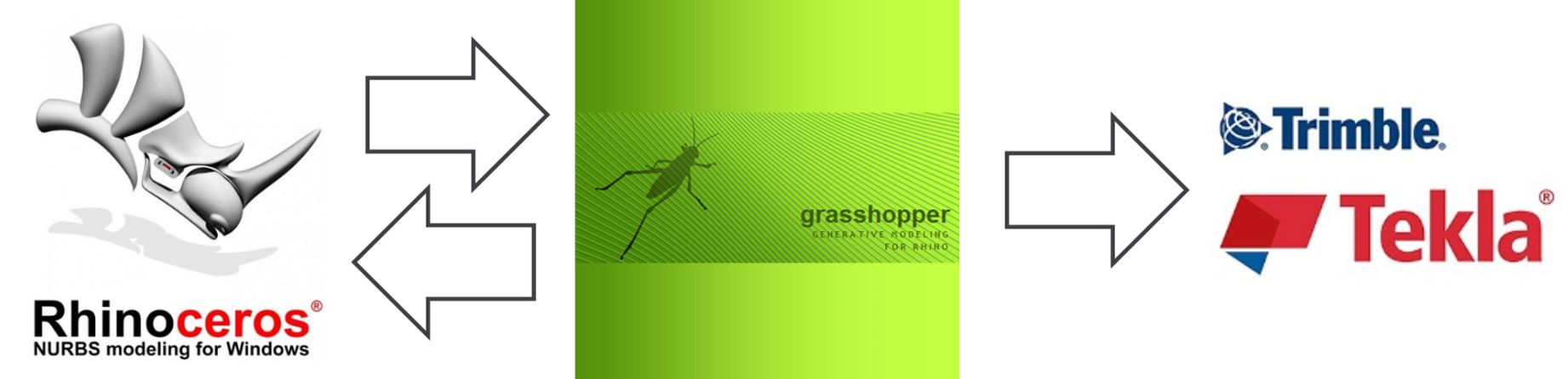
Grasshopper Software
Grasshopper is a visual programming language and environment that runs within the Rhinoceros 3D software. Visual programming lets humans describe processes using illustrations or graphics. This type of programming is based on the idea of “boxes and arrows.” Boxes or other screen objects are treated as entities, connected by arrows, lines or arcs, which represent relations.
Grasshopper with Tekla
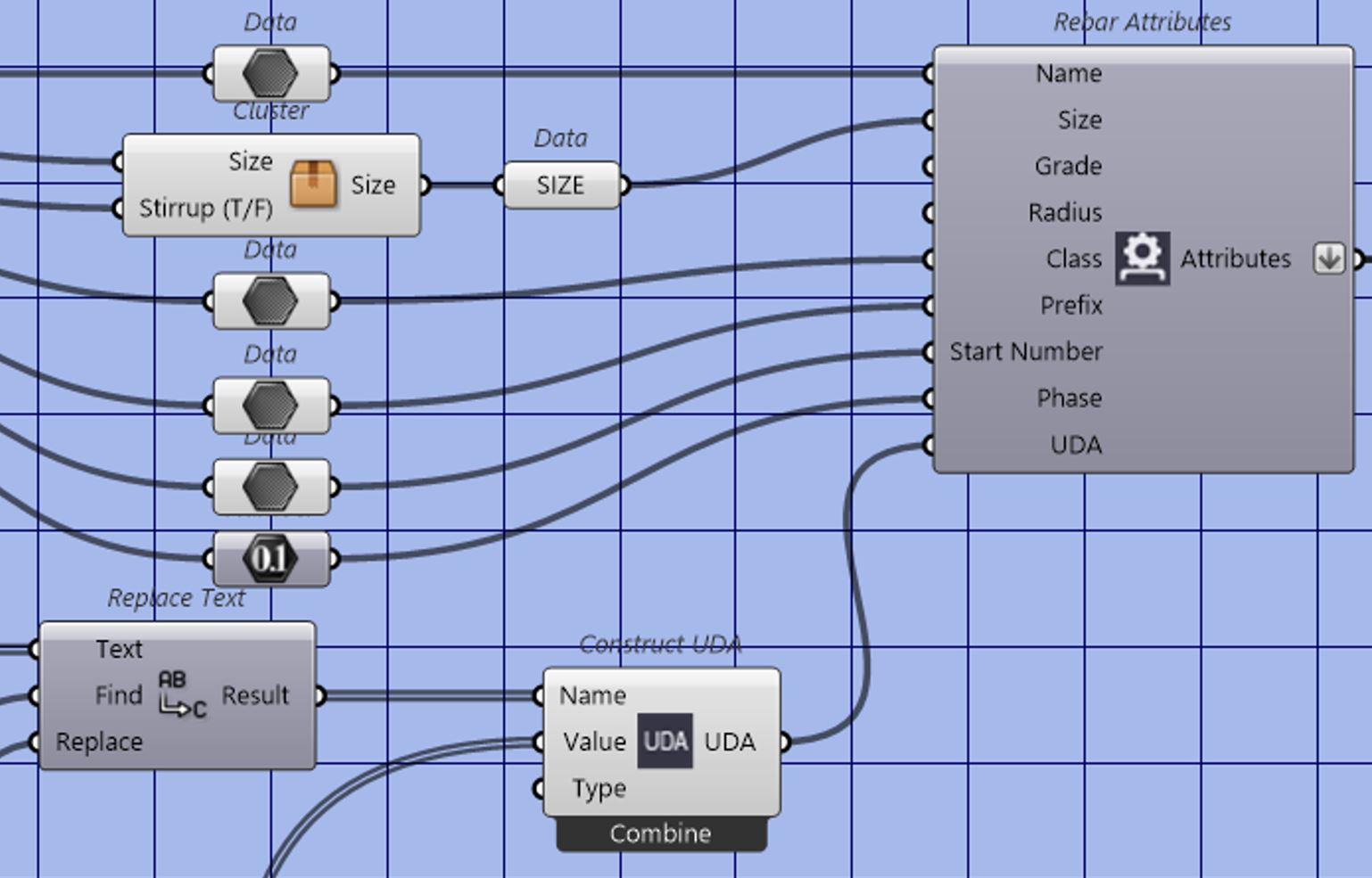
What is essential with Grasshopper-Tekla live link is the fact that it creates and manipulates native Tekla objects. This functionality was crucial to the great success of this connection. Together with geometry, all types of reinforcement can be created through Grasshopper. All data that defines reinforcement in Tekla can be manipulated from the Grasshopper level. Including creating reinforcement in tapered or curved form.
Not just creating advanced geometry and reinforcement was the key to success here. Grasshopper can query for all Tekla model information. BIM data, attributes and object placements can be changed in real-time. It is possible to extract all UDA (user-defined attributes) from Tekla to Grasshopper and another way around.
How could Grasshopper users work simultaneously in the same file?
Grasshopper does not have a cloud model-sharing option. Maybe in the next version. We hope so! On the Randselva Project, we had to work without it. Grasshopper components data output/input came to rescue us.
Step-by-step process of using Data input/output
– Take into canvas component called data output.
– Connect data to the component in order to share with other users (zoom into the component to add extra inputs),
– Save a .ghdata file with others on your server.
– Every time we change data in the component, the .ghdata file will be updated automatically.
– Consequently, if someone has started writing their own script, they can easily download data from the file by choosing the correct destination of .ghdata
If someone’s work depends on information from someone else, they simply ask for the .ghdata file, not for the whole script. The biggest advantage is that the data output is updated in real-time, and thus, all the users work on the latest version of data.
3.7. Correct information in the correct place
BIM methodology early in the design phase must be coordinated and developed in cooperation between the designers and project engineers from the contractor. The amount of information must be agreed upon so that during the construction stage the workers and staff will be capable of successfully using and analyzing data from the digital interpretation of the structure.
In order to achieve that, we can create user-defined attributes (UDA). Attributes are associated with all objects in a BIM model and the program that was used to model the object automatically predefined some of the attributes. Objects can also be enriched with project-specific UDA as shown in the table below.
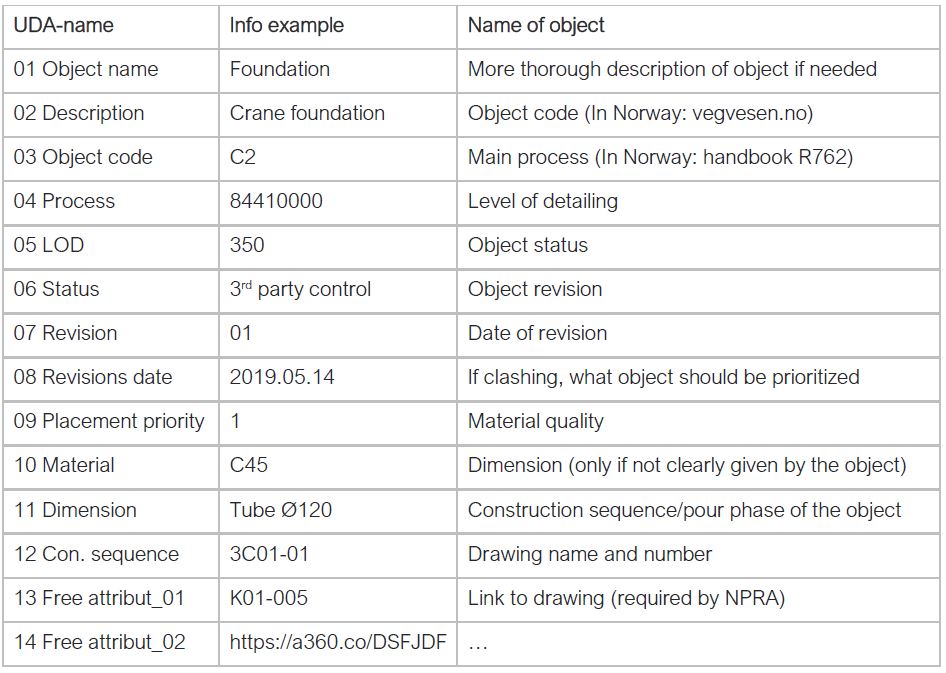
One of the most important parts of constructing a high-quality BIM model is adding useful attributes to objects in the model. The more structured data is added, the easier it is to use the model at later stages. On the downside, a large set of attributes is hard and laborious to maintain. The key is understanding what kind of information is useful at different life stages of the BIM model.
In an IFC-viewer like Solibri, these attributes are shown when marking an object. For the Randselva Bridge project, the user-defined attributes were shown in the custom-made curtain “A_E16_PART_INFO” seen in the below figure.
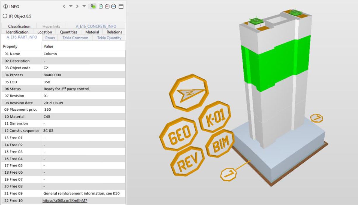
In the project, one of the most used UDA was “construction sequence“. This attribute states which cast unit the object belongs to. This enabled the contractor PNC Norge to plan their orders of concrete, reinforcement, and post-tensioning in a better way, making logistics at the site easier.
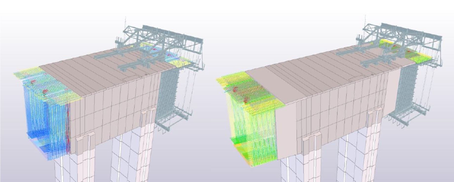
The figure below shows the BIM simulation of the first two-deck segments in Axis 3. As the BIM model moved through its life stages, the type of user-defined attributes needed for an object will most likely change due to revised requirements. Changing user-defined attributes for objects in the BIM model is relatively easy.
3.8. Close cooperation with the contractor
In a design & build contract, it is a prerequisite to have close cooperation between the designer and the contractor. It was also a case for the Randselva Bridge, where the project size and complexity required good communication and understanding between all the project stakeholders.
Early in the tender stage, the main contractor PNC Norge, after preliminary meetings with the lead design company, Sweco, decided to execute the project model-based. Since at that time, there were few reference projects and none of its size, it was a decision that led to big consequences when it came to cooperation on this design & build contract.
When doing anything innovative, we need to find new ways of doing things. Designing, and then constructing a bridge of this size required that everybody on the team ‘raise the bar’, or give that little extra that is needed to achieve success. For instance, the designers had to think in a new way: if I do not create drawings, but the model, how can I give all the necessary information for building to the construction site? The contractor faced a similar challenge: how can we build a project without drawings?
The challenge of the drawing-less methodology is a collaboration to be set between all people and make them work as a team. Everyone should go for the same rules and have the same goals. Thanks to close cooperation and internal meetings, the designers were able to understand the contractor’s needs and produced the models that could later be used on the construction site.
Summary of second part
In this second part of the series about Randselvabru – the world´s longest bridge built without drawings we had a look at the remaining solutions to the challenges of this model-based project:
- ICE sessions and hackathons
- Parametric design
- Correct information in the correct place
- Close cooperation with the contractor
Stay tuned for the next part, where we will cover the solutions for the challenges on the construction site!
Bibliography
In the creation of this series and the case study, we have used the following sources:
- RANDSELVA BRIDGE: PLANNING AND BUILDING A 634m LONG BRIDGE SOLELY BASED ON BIM MODELS Øystein Ulvestad, Sweco Norge AS Tiago Vieira, Armando Rito Engenharia SA
- RANDSELVA BRIDGE: CONSTRUCTION WITHOUT DRAWINGS Wiktor Rybus, BIM Developer, Sweco Norway (until 01/2022 PORR/PNC)
- https://e-brim.com/randselva-bridge-digital-twins-bim-in-south-korea/
- https://www.ringeriksavisa.no/arkiv/item/8429-randselva-bru-apner-uten-budsjettsprekk
- Authors of some of the photographs: Ståle Savland (SVV), Konrad Naborczyk (BIM Corner/Skanska
- Renderings: SWECO