10 Common IFC Export Mistakes to avoid – part 2

In the previous part we looked into five of the most common mistakes while performing IFC export. This entry encompasses five next. Together they create an “Ultimate list of IFC export failures” 😉

As in previous article, to underline the versatile ways to achieve the same results, I used screenshot examples from a range of software programs as well as different projects, models and disciplines.

Table of Contents

6. Exporting too many properties

“It’s better to have too much data than not enough, right?” or “Oh! I’m missing this one property in IFC table mapping, but I have it in my Revit parameters, so I just export them all!” If those thoughts appear in your mind while doing IFC export, please stop. 😉 We don’t export native properties, schedules as properties and additional IFC properties. Otherwise, working with data is difficult, models are heavy and inefficient.

Data is most useful when it is correct and with the correct amount. Too little is bad and too much is not correct either. ISO 19650 coined the term “Level of Information Need”, where the Building Owner specifies what and how detailed data is sufficient for the Owner’s need. Translating it down to the level of the project – each one has its own EIR (Exchange Information Requirements). The Building Owner specifies the whole list of properties required in the project. However, on the discipline interferences, there are often required some more parameters. But then those, not necessarily, are included in IFC export for a construction site (shared state).

Revit IFC export
Revit IFC Exporter. That is not the correct setting. Most of the time, you are well enough with checkboxes marked red.
Native properties
Objects with exported native Tekla project properties (here we have the doubled-up quantity properties both in Solibri native tab and from Tekla).

How to check and avoid this IFC export mistake

Checking if there are not too many properties is easy: just open the IFC viewer and EIR document and do a quick run-through of property sets. Unwanted properties are usually in separate tabs for property sets.
To avoid this IFC export mistake, create a “how-to” instruction. I recommend developing one such standard for each software used during the design process (hopefully following the checklist from this entry). Assess also a need to define a common property for quantities because different software uses different Property Sets to export quantities (ref. Screenshot above).

7. Lack of required properties

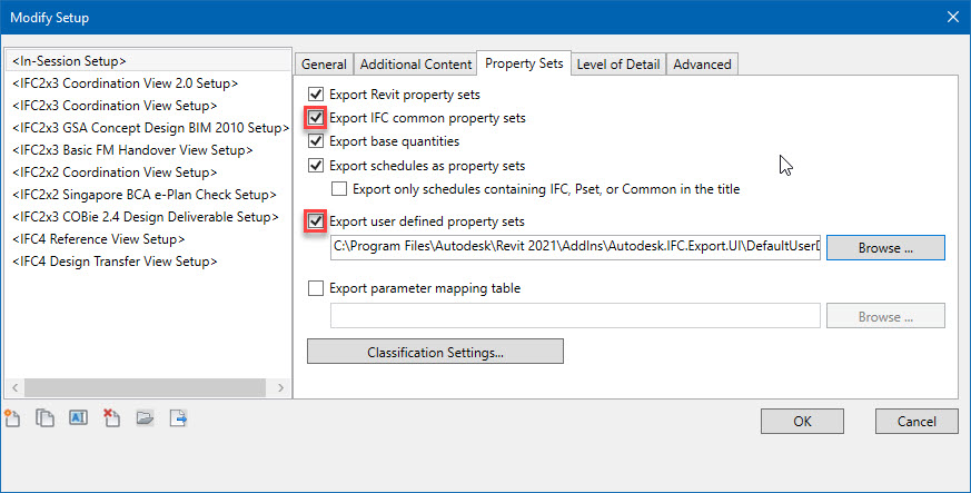
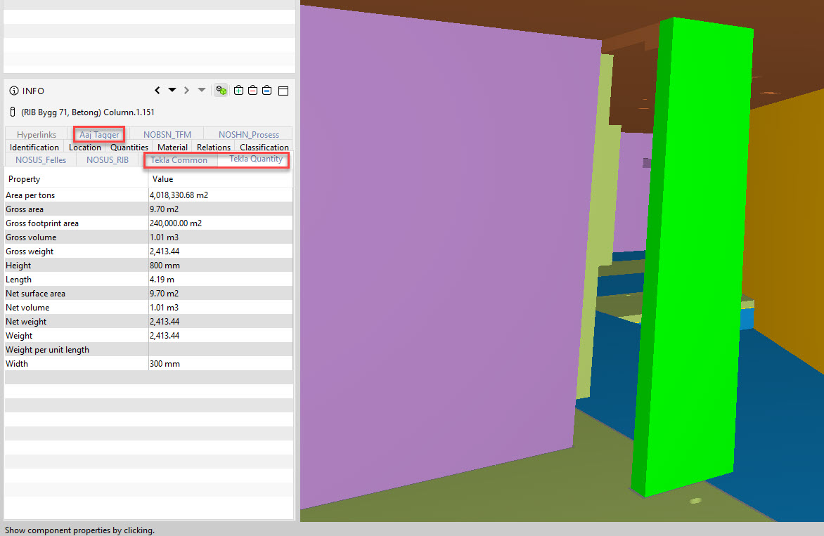
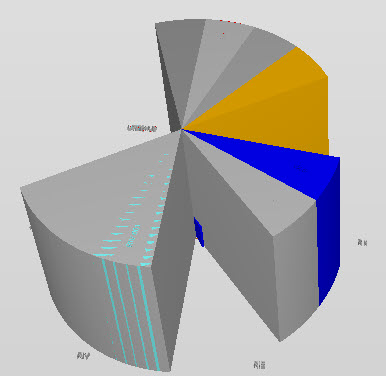
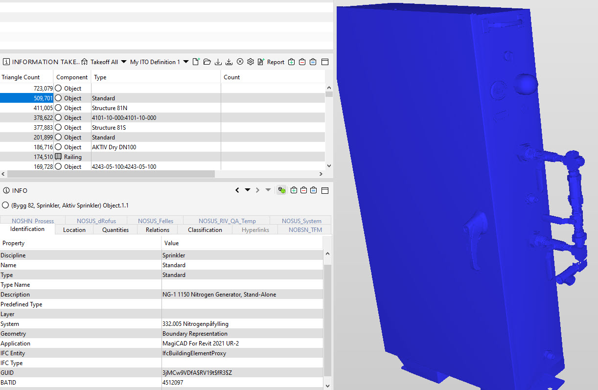
A point that is contrary to the one above. Here, the designer responsible for export has checked none of the checkboxes from the screenshot above. Especially he/she forgets about project defined IFC property sets. The model contains then only default IFC properties, such as type name and quantities. Default properties are not enough for the BIM project that aims to use the model during the following project stages. The list of required properties for the whole project is much longer (calculation basis, reference properties, status codes, control area, responsible contractor, etc.)
IFC viewer (here BIM Vision). Take a look at the table on the lower right. This element has only generic properties exported (Element Specific, Profile and default Psets).
Correctly exported objects with all required project property sets (those in the table starting with NO).

How to check and avoid this IFC export mistake

Checking for the properties is similar to the point above – open the file and check what property sets are included. To avoid this mistake, again, set up your IFC exporter in such a way that it includes required properties. BIM Manager/BIM Coordinator should, therefore, translate properties defined in the EIR document into template files for each software used in the project (Here is an article on how to do it in Revit). Different tools have different ways of achieving this. In some, we create properties directly in the model, in others, we have to create a mapping table.

8. Incorrect model rotation and base point placement

There is nothing satisfying in sending the model back to a designer on Monday morning after receiving the model on Friday afternoon. One of the reasons this happens is having them incorrectly placed or rotated. This is especially common for new models added to the project.

Always follow the project guidelines. Every software has its own way to specify the survey point and true north for the model.

Revit coordinate base
IFC Exporter in Revit. Dialogue to choose Coordinate Base for the export.

In Revit, there are a few possible options. In a very, very short description, those coordinate points are:

  • Shared Coordinates – if all the models share the same coordinates related to the real world coordinates it is best to export IFC using this as a Coordination Base. The models have to have synchronized coordinates beforehand to use this base. This is the most common way of cooperating between multiple models.
  • Survey Point – it typically represents a “known point in the real world.” or if you prefer “an anchor between our model and the coordinates in the real world”. The whole project can refer to that point.
  • Project Base Point – local building coordinates. You can choose the point that is most convenient to the project team. Often placed by the building’s bottom left corner. Unfortunately also often happens that different branches use different Project Base Points.

More information about the topic:

How to check and avoid this IFC export mistake

The best way to check it is to federate the models. Additionally, if you have the right software, running a simple collision check is also handy – if models are displaced, you will receive lots of clashes that greatly exceed the normal amount (for example, switchboards placed within the wall or ventilation canals overlapping with piping).

To avoid the mistake, follow the BEP description and set-up coordinates, true north and survey point. It is also smart to create origin point objects for each discipline and check if they fit together. I believe it is easier than looking at the models themselves to check if they are aligned.

Origin Point
Federated origin points for different models.

9. Exporting too detailed geometry

Objects’ level of detail in the model is the performance issue. This is especially important for bigger projects with many models and objects. Design and construction models are not meant to look nice. Their main goal is to serve as a basis to conduct work on-site and spatial coordination. This means that geometrically we need merely their space usage and possible clashes.
If the model is overloaded with fine-detailed objects with many triangles, it slows down the performance of IFC viewers and helps with nothing. This mistake is often made by industrial engineers that are designing specific off-site prefabricated elements. Huge boilers, chimneys or other steel structures. This may also be an issue when using ready-made suppliers’ object libraries full of detailed geometry with bolts and notches.

However, with BIM-advanced, complex projects with many properties, geometry can be responsible only for as little as 20% of the model weight. But those projects have to put great attention to every possibility to reduce model weight and increase the performance of the federated models.

Too detailed geometry
This guy tops the list with over 500 thousand triangles. Do you see those fine details on the side? Yeah, we don’t need them 😉

How to check and avoid this IFC export mistake

In Solibri, in the Information Take-Off tab, you can add a column with a triangle count. If you have doubts about model performance it is good to check if there are not too many objects with too detailed geometry.

If you receive a family/library object from a manufacturer or other ready-made library, check beforehand how detailed it is to avoid loading in the models too detailed geometry.

triangle count
Information take-off performed in Solibri with sorting after triangle count.

10. Incorrect IFC schema

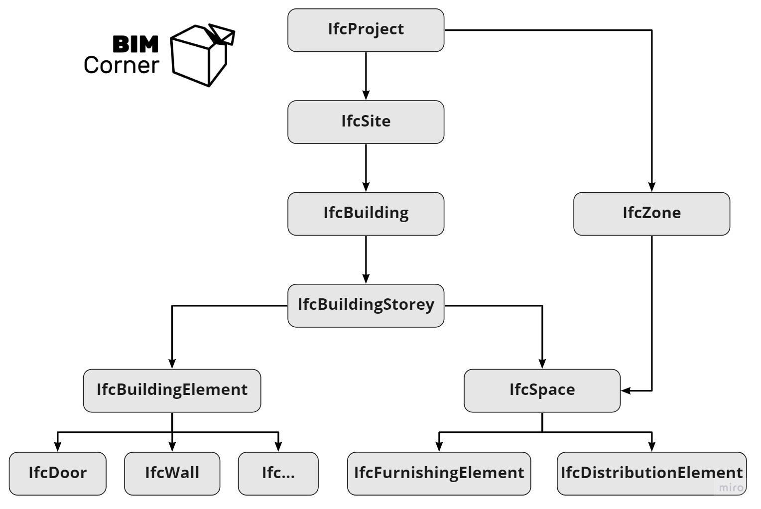
The data structure is important in BIM projects. One of the reasons is a cooperation between different software. If you want seamless data flow, you have to structure your data correctly – according to the common standard (IFC schema). The geometrical objects have to belong to the spatial hierarchy of the model. The hierarchy is shown below.
IFC inheritance tree
IFC inheritance schema. Own graph based on the information available at https://standards.buildingsmart.org/
What happens if this is not correct? A good example is sending an IFC model to Facility Management software. Room equipment (IfcFurnishingElement) should be placed under IfcSpace. If it lies directly under IfcBuildingStorey together with walls, doors, then after sending such a file to the aforementioned FM software, it may read the room as empty. Geometrically it is not true, but data-wise, IfcSpace is indeed empty for objects (nothing underneath IfcSpace in the schema). It may sound a little bit complicated at first, but the graph below should help. Such export errors are sometimes predicted by some software that actually graphically searches for objects within the space and returns results. Not all software can do that though. And this time, it is not a software error.

How to check and avoid this IFC export mistake

To check IFC spatial structure, just open one of the IFC viewers described previously, expand the IFC tree schema and check if everything looks in accordance with the graph above (e.g. objects not under building stories but under IfcBuilding).
Avoiding this issue might be more tricky since this is often tied with how the software works and exports IFC. In some software (e.g. ArchiCAD) it is possible to check IFC structure before the export and manipulate it to satisfy our needs. More about this in our IFC export for ArchiCAD guide.

Summary

In this two-part entry, I’ve presented you with the 10 most common IFC export mistakes. This part covered a few topics about the correct level of information and its structure. From my experience, I find it extremely important. Working on a big project with many stakeholders and huge data sets I see every day how important it is to follow guidelines. Ultimately, how this helps with data management and workflow between different software.

I encourage you to be strict about data, how it is produced and its level. The construction branch still has a long way to walk in this area.

10 mistakes in IFC Export
List of 10 most common IFC export mistakes

Check out the series about IFC Export:

1. PART – Why is it important?

2. PART – What to export?

3. PART – How to do it?

a. Tekla

b. Revit

c. Archicad

4. PART – IFC Export Mistakes and how to avoid them

Mistakes 1-5

Mistakes 6-10

Did you like that post ? Share it with others !

We spend a lot of time and effort creating all of our articles and guides. It would be great if you could take a moment to share this post !

Share:

Comments:

Subscribe
Notify of
guest
1 Comment
Oldest
Newest
Inline Feedbacks
View all comments

Author:

Download BIM CASE STUDIES:

After reading this guide you will learn:

  • How BIM is used on the biggest projects in Norway
  • What were the challenges for the design team and how were they solved
  • What were the challenges on the construction site and what was our approach to them

Newest articles: