

Everyone who works with IFC has heard that the format carries more than geometry. Properties, classifications, relationships, materials. Fine.
Almost nobody mentions that it also carries time.
Not as a linked Primavera file. Not as an exported spreadsheet that has to be re-imported somewhere else. As proper entities, inside the same file as the geometry. Which means that if the data is there, you can watch the structure build itself – and you do not need a single commercial licence to do it.
This article walks the whole thing, start to finish, by clicking. Where the schedule sits in the file, how to play it back, how to build one from scratch if your model has none – and the three things that went wrong when I made this film.
Starting point – where the schedule actually sits in the file
Let us start with the thing that catches almost everybody the first time. You open an IFC file in a viewer, expand the tree, and there is no schedule anywhere. That is not a bug. It is not where you are looking.
The tree you see in a viewer is the spatial structure – project, site, facility, its parts, and the physical elements inside them. A schedule does not belong there, because a task is not a thing standing in space. It hangs off the project on a separate branch.
- IfcProject
- ├─ IfcRelAggregates → IfcSite → IfcBridge → IfcBridgePart → elements
- │ this is what your viewer’s tree shows
- │
- └─ IfcRelDeclares → IfcWorkPlan → IfcWorkSchedule → IfcTask
- this is what it does not – and this is where 4D lives
Two branches of the same project. Geometry on one side, time on the other. They never meet until IfcRelAssignsToProduct makes them.
That is where the “there is nothing in the file” impression comes from. An ordinary viewer shows one branch and stops. To see the other one you need a tool that reads it – and that is what the rest of this article is about.
The links themselves are simple, but each one does a different job:
| Link | Connects | What it is for |
|---|---|---|
IfcRelDeclares |
project → plan and schedule | attaches the schedule to the project, outside the spatial structure |
IfcRelAssignsToControl |
schedule → tasks | says which schedule a task belongs to |
IfcRelNests |
task → sub-task | builds the stage hierarchy |
TaskTime attribute |
task → IfcTaskTime |
the dates; not a relationship, just an attribute of the task |
IfcRelAssignsToProduct |
element ↔ tasks | the only place where time meets geometry |
IfcRelSequence |
task → task | dependencies and lag |
One direction is worth memorising, because it reads backwards from what you expect: in IfcRelAssignsToProduct the product is the physical element and the related objects are the tasks. You read it from the element to the task, not the other way round.
IFC 2×3 cannot do this. Open the 2×3 version of the same bridge and the scheduling panel does not appear at all – whatever the file contains. This whole article assumes IFC 4.3.
Part 1 – What 4D in IFC actually is
The most common misunderstanding goes like this: 4D is “the model plus a schedule sitting next to it”. It is not. There is no link to an external file, no ID matching, no shared spreadsheet. The schedule is in the file, as first-class objects, and the connection between a task and an element is an explicit relationship object – exactly like the one that puts a column inside a storey.
Five entity types carry the whole thing.
- IfcWorkPlan “Construction plan BR-01”
- └─ IfcWorkSchedule “Construction schedule BR-01” [PLANNED]
- ├─ IfcTask ×17 what happens
- │ └─ IfcTaskTime when it happens
- ├─ IfcRelNests stage → sub-task
- ├─ IfcRelSequence ×14 what waits for what
- └─ IfcRelAssignsToProduct task → physical element
The complete 4D structure of the bridge file. Seven lines. That is all there is to it.
A task and its time
A task is deliberately thin. It holds a name, an identification code, a predefined type, and a pointer to a separate object that carries the dates. Two details are worth knowing, because they catch people out.
First, the predefined type – usually CONSTRUCTION – is not decoration. It says what kind of work this is: construction, demolition, logistics, installation. A 4D tool uses it to pick the colour. Leave it as NOTDEFINED and your demolition sequence animates in the same green as your new build.
Second, IfcTaskTime has twenty attributes and an animation needs three: duration, schedule start and schedule finish. The rest – actual start and finish, early and late dates, float, percentage complete – only matters once you compare against as-built.
Assigning tasks to elements
A schedule with no connection to geometry is just a schedule. The connection is IfcRelAssignsToProduct, and it is what turns dates into an animation. In the bridge file the assignments look like this:
| Task | Name | Elements | Classes assigned |
|---|---|---|---|
T10.1–T10.6 |
Foundations, per support axis | 3 each | IfcFooting, IfcSlab, IfcEarthworksFill |
T20.1, T20.6 |
Abutments A1 and A2 | 3 each | IfcWall |
T20.2–T20.5 |
Piers P1 to P4 | 1 each | IfcColumn |
T30 |
Deck casting and bearings | 7 | IfcBearing, IfcBeam, IfcSlab |
T40 |
Edge beams and approach slabs | 14 | IfcBeam, IfcSlab, IfcEarthworksFill |
T50 |
Railings and equipment | 2 | IfcRailing |
Add it up and you get 51 elements. The bridge has 151. Hold that gap – we come back to it in Part 3.
Dependencies between tasks
Dependencies are their own objects. IfcRelSequence points from a preceding task to a following one and carries a type:
| Type | Meaning | Used in this file |
|---|---|---|
FINISH_START |
B starts when A finishes. The default in any programme. | 4 × (between stages) |
START_START |
B starts when A starts. Parallel work. | 10 × (inside stages) |
FINISH_FINISH |
B finishes when A finishes. | – |
START_FINISH |
B finishes when A starts. Rare, and usually a mistake. | – |
Each dependency can also carry a lag (IfcLagTime) – the offset between the two events. Concrete curing before striking formwork is a lag. None of the fourteen dependencies in this file have one, and in Part 3 you will see what that does to the animation.
Part 2 – Step by step in Bonsai
Bonsai – formerly BlenderBIM – is a free, open-source add-on that turns Blender into an IFC working environment. It reads the schedule natively and can animate the model directly from it. Everything below is clicking in the interface; the screenshots are from Blender 5.1 with Bonsai 0.8.5.
The numbers on each screenshot match the numbers in the list underneath it.
Step 1 – Install and load the model
Install Bonsai from Blender’s own extensions platform: Edit → Preferences → Get Extensions, search for Bonsai, install. Restart Blender. You get a new BIM tab in the top bar.
Then File → Open IFC Project and pick your file.
Step 2 – Open the scheduling panel
This is where most people get stuck, because it is not where you would look for it. The scheduling tools are not in the sidebar of the 3D viewport – they sit in the Properties editor, on the Scene tab.
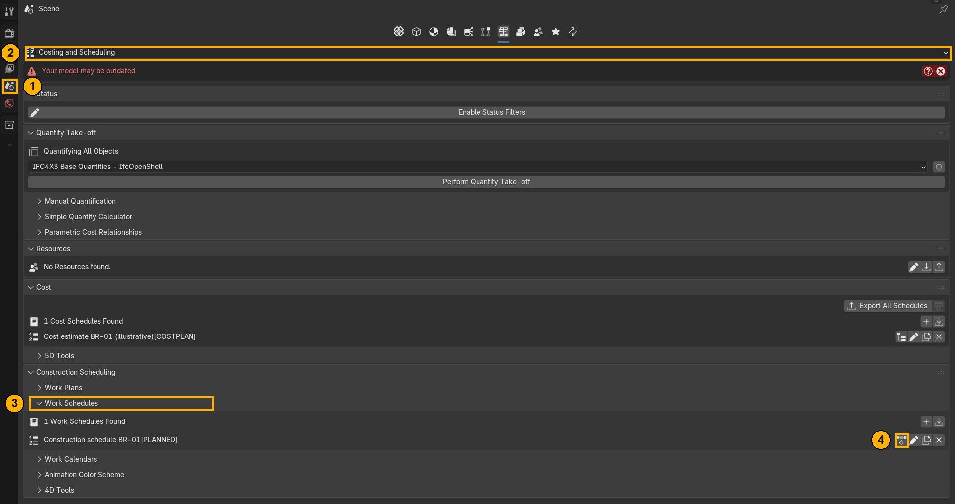
- 1
Scene tab
Everything Bonsai adds to the project lives here.
- 2
Dropdown → Costing and Scheduling
Switches Bonsai to the 4D and 5D panel group.
- 3
Construction Scheduling → Work Schedules
Expand it. You should see how many schedules were found and the name of the one in your file.
- 4
First of the four small icons
This is the one that opens the task tree. The others are rename, duplicate and delete – none of them will open the schedule.
The icons have no labels, and the Properties column is too narrow by default, which clips the button text. Drag it wider before you start, or you simply will not see half of what is there.
Step 3 – Set the date range and the speed
Once you are editing the schedule, the task tree appears, and below it a section called Animation Tools. It is collapsed by default and does not exist at all until a schedule is active – if you cannot find it, step 2 did not take.
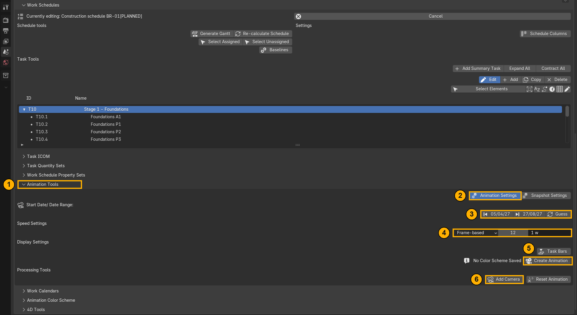
- 1
Animation Tools
Expand the section.
- 2
Animation Settings
Animation mode. The neighbouring Snapshot Settings gives you one date instead of a sequence.
- 3
Guess
Reads the earliest start and latest finish from the tasks and fills in the date range. Do not type the dates by hand.
- 4
Speed
Pick Frame-based and read it as “this many frames buys one week of site time”. 12 frames per week turns this programme into roughly ten seconds of video.
Step 4 – Create the animation and watch it
Same panel, further down:
- 5
Create Animation
Writes the keyframes onto the model. This is the button.
- 6
Add Camera
Drops in a camera aimed at the model. You will want it for the render.
Press Spacebar to play. Dragging the timeline jumps to any date.
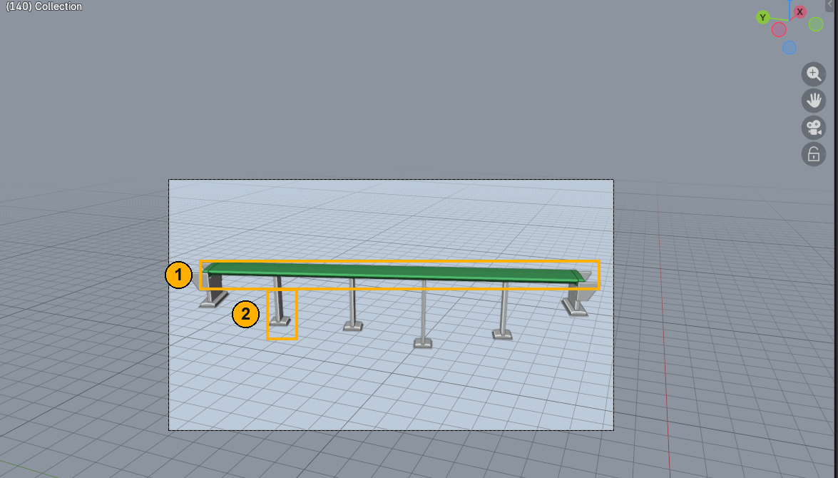
Why the colours appear at all. Bonsai does not animate visibility or materials – it animates the object colour. Create Animation also flips the viewport shading to object colour on its own. Without that, the animation would run perfectly and you would not see a thing. If you ever meet a model that sits still with play pressed, check this setting first.
Step 5 – Render the film
Bonsai builds the animation in the scene but does not render it – that part is plain Blender. The right engine is Workbench: it draws object colour directly, which is exactly what Bonsai animated, and it is by far the fastest.
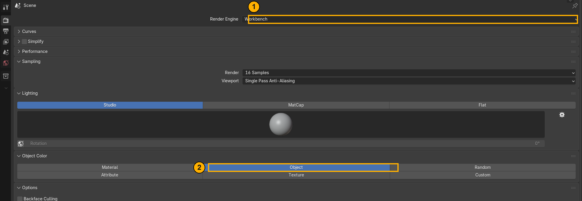
- 1
Render Engine → Workbench
Renders object colour, with no materials or lighting to set up.
- 2
Color → Object
Without this the render ignores the animated colours and you get uniform grey.
- Properties → Output – set the resolution. The frame range is already correct.
- Media Type → Video. Until you switch this, the video format does not appear in the list.
- File format FFmpeg Video, then container MPEG-4 and codec H.264.
- Render → Render Animation.
Step 6 – And if your file has no schedule at all
Everything above assumed the schedule was already in the file. If you have a bare export – geometry only – you build it in the same panel, in this order. Each step names the entity it creates.
- Add a schedule. In the Work Schedules section press the plus. That creates
IfcWorkSchedule. Then the first icon on its row for task editing mode – same as in step 2. - Add a stage task with Add Summary Task. One per construction stage. That creates
IfcTask. Give it a readable code, because that is what you will navigate by for the rest of the job. - Add sub-tasks with Add, with the stage selected. That creates
IfcRelNests. This is where the real breakdown of the work goes: foundation by foundation, support by support. - Enter the dates. Select a task, Edit, then the clock icon, and fill in schedule start and finish. That creates
IfcTaskTime. A task with no dates cannot go on a timeline. - Assign the elements. Select objects in the 3D viewport, select the task, and add them in the Task ICOM panel under Outputs. That creates
IfcRelAssignsToProduct. This is the step that turns a schedule into a 4D model – everything before it was just a list of dates. - Add dependencies. Edit, then the crosshair icon, and point at the predecessor or successor. That creates
IfcRelSequence. - Save the IFC. All of the above lands in the same file as the geometry. No companion file is produced.
Check one thing before you build the whole schedule. If your model contains assemblies – railings, trusses, precast units made of parts – assigning a task to the parent does not cover its children. That is exactly the trap the next part opens with, and it is much cheaper to know about it before you have built the entire programme.
Free live webinar
IFC 2×3 vs IFC 4.3
One bridge. Two schemas. Everything that changes.
The schedule you have just seen is one of six information layers I built into this bridge. On 5 October I open the same model live and read the other five – alignment and stationing, bridge parts, bearings, material profile sets and the structural analysis model – next to the IFC 2×3 version of the identical geometry.
Then a five-step framework – Understand, Structure, Export, Inspect, Verify – to run before your next delivery.
Monday 5 October 2026 · 19:00 CEST · 60 min + live Q&A
Free. The recording and the slides go to everyone who registers, whether or not you make it live.
Part 3 – The three things that broke
Everything above is the documented path. What follows is what actually happened when I made this film. None of the three announces itself – the animation just comes out wrong.
Trap 1
The railings were there from the first frame
Stage 5 installs the railings. In the first version they were standing on the bridge before the foundations were poured.
Remember the gap from Part 1: 51 elements assigned, 151 in the bridge. The 100 missing ones are the railing posts. The task points at the railing as a whole, and its posts hang underneath it as separate elements that do not inherit the assignment. Bonsai never touches them, and an element nobody touches stays visible from frame one.
How to fix it: select the posts in the 3D viewport, select the task in the tree, and add them under Task ICOM → Outputs, exactly as you assigned everything else.
The general lesson is worth more than the fix itself: after you build an animation, count the elements that actually have a task. Not the ones the schedule mentions – the ones that got animated. If the two numbers differ, something is on screen at the wrong time.
Trap 2
The “in progress” colour flashed and vanished
Green is supposed to mark work in progress for the whole duration of a task. It appeared for a few frames and faded to white.
Bonsai writes one colour at the start of the task and another at its finish, and Blender blends smoothly between them by default. An element does not hold green for its 45-day deck pour – it starts green and spends most of the task somewhere between green and white.
How to fix it: state is not a gradient; an element is either under construction or it is not. Select the colour keys in the Dope Sheet and set interpolation to Constant – the colour then holds and jumps instead of bleeding.
Trap 3
Six foundations appeared in the same instant
Then nothing moved for three seconds. Then six piers at once. The film looked broken – and the data was completely valid.
This one is not the tool’s fault. This one is the schedule, and it is the most useful of the three, because it is the one you will hit on real projects.
| Task | Name | Start | Finish | Duration |
|---|---|---|---|---|
T10 |
Stage 1 – Foundations | 2027-04-05 | 2027-04-29 | 25 d |
T10.1 |
Foundations A1 | 2027-04-05 | 2027-04-09 | 5 d |
T10.2 |
Foundations P1 | 2027-04-05 | 2027-04-09 | 5 d |
T10.3 |
Foundations P2 | 2027-04-05 | 2027-04-09 | 5 d |
T10.4 |
Foundations P3 | 2027-04-05 | 2027-04-09 | 5 d |
T10.5 |
Foundations P4 | 2027-04-05 | 2027-04-09 | 5 d |
T10.6 |
Foundations A2 | 2027-04-05 | 2027-04-09 | 5 d |
All six sub-tasks have identical dates, and the dependencies between them are START_START with no lag. That says, precisely and correctly: these six things start at the same moment. So the animation shows six foundations appearing simultaneously. It is not wrong – it is a faithful rendering of a programme that says all the crews pour on the same Monday.
There is a second symptom in the same table. The sub-tasks occupy 5 days of a 25-day stage. Nothing is scheduled in the remaining three weeks, so the film holds a static image while the calendar burns through a month.
Two ways out, and they are genuinely different decisions:
- Stagger the dates. If the work really does move along the bridge – A1, then P1, then P2 – the sub-task dates should say so. This is a planning fix, and it is the honest one.
- Add lag. Keep
START_STARTand give each dependency a few days of lag, so the crews follow each other rather than starting together.
Which brings out the real point of building a 4D animation in the first place.
A programme in a Gantt chart with everything starting on one date looks perfectly normal – six bars, neatly aligned, nobody blinks. The same programme as a film is instantly, physically implausible: six separate foundations, seventy metres apart, materialising in the same frame.
4D is not a presentation tool. It is a review tool. The animation is how you notice that the schedule says something nobody meant.
Try it on your own file – five checks
- Is there a schedule at all? Open Work Schedules. Zero found, or no panel at all, means there is no 4D data, and no amount of software will invent it.
- Do the tasks have dates? Turn on the columns with Schedule Columns and run your eye down the tree. Empty start and finish fields are tasks that cannot go on a timeline.
- How many elements have a task? Select Unassigned selects everything with no task on it. It is the fastest 4D data check there is.
- Are assemblies covered? After the previous check, look at whether parts of assemblies are sitting in the selection. That is where Trap 1 lives.
- Do the task types make sense? If everything changes to one colour when the animation runs, the predefined types are empty and no phase of work will stand out from any other.
About this model. The bridge geometry comes from a real Tekla Structures export. The semantics – schedule, materials, classifications – were built on top of it for teaching, and the values are illustrative: concrete classes, dates and the client are examples, not design data.
About viewer support. IFC 4.3 scheduling is well defined in the schema, but reading it is another matter. Bonsai handles it properly. Several mainstream viewers still ignore the schedule entirely, or show the tasks without connecting them to elements. Check what your own toolchain does before you promise a client 4D deliverables.
What this actually demonstrates
A twelve-second film is a nice thing to have. It is not the point.
The point is that a single IFC file carried the geometry, the classification, the quantities and the schedule of one bridge – and a free add-on read the schedule out of it and animated the structure without anyone retyping a date.
That only works when the information is in the model. Click Export to IFC on a model with no types, no quantities and no schedule, and you get a shape. Everything in this article would have had nothing to read.
Free live webinar
IFC 2×3 vs IFC 4.3
Why your infrastructure model finally makes sense to the client
I take this bridge – the same 87 metres, the same geometry to the millimetre – exported three ways: a careless IFC 2×3, the best IFC 2×3 the schema allows, and full IFC 4.3. Then I read all three side by side on screen.
Alignment and stationing. Bridge parts instead of building storeys. Bearings that are bearings. The schedule you have just seen. And the number that surprises everyone: the worst file is three times larger than the best one, and carries no information at all.
Monday 5 October 2026 · 19:00 CEST · 60 min + live Q&A
Free. The recording and the slides go to everyone who registers, whether or not you make it live.
If you want to go further than one example, the IFC Infrastructure Masterclass works through the whole delivery workflow across six workshops – objects, relationships, properties, classification and information structure, on real infrastructure models.