

Welcome to the last, fourth part of the “IFC export from Revit” article series. If you haven’t checked previous posts about this topic, I recommend you to read them.
Part 1 – Mapping
Part 2 – Top-Level IFC entities
Part 3 – User-defined properties
In this final article, we will take a closer look at the options within the Revit exporter. Before we will hit the export button to create an IFC file, we need to configure IFC Exporter in an appropriate way.
My intention isn’t to go through all the settings of the IFC exporter but only these that you most probably will use during your work. However, a list of all the settings can be found here.
The article is a complementary part of the video lesson which is available here:
This lesson comes from the BBC – Become BIM Coordinator course which I am an author of.
If you are interested in a BBC online traning and would like to know more, visit the course website, where you can find all the details about this extensive online training.
DO YOU WANT TO BECOME A BIM COORDINATOR ? JOIN MY FREE WEBINAR SESSION WHERE YOU WILL LEARN A LOT ABOUT IT
Revit IFC Exporter
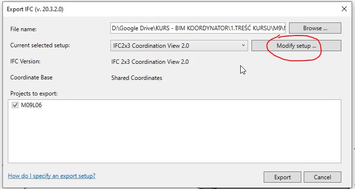
So now, let’s jump to Revit and see what IFC Exporter has to offer. To set up export options, first, we need to click Modify Setup button.
On the left you have a list of pre-defined setups that you can use, or duplicate and edit it in a way you like.
If you want to start from a “blank page” you need to use In-session Setup (number 1 on the picture below)
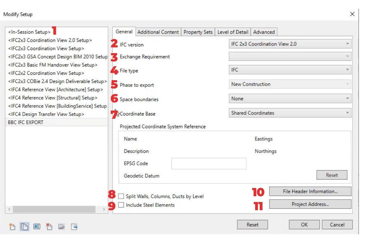
General Tab
In the general tab, we can specify the IFC version and the exchange requirements. (number 2, 3 ).
As IFC Version I usually set IFC 2×3 Coordination View 2.0 or IFC 4 Reference View.
Next, we have a file type (number 4). The file type determines the file format in which the exported file will be saved. I usually use IFC (STEP format) but for big projects, the compressed *.ifczip format can be used, which is also supported by most IFC viewers.
Then we set up a phase (number 5)that we wish to export. The default phase is the last phase that is used in the project. Which one you are going to choose depends of course of your needs and models breakdown structure.
The spatial boundaries (number 6) option determines how room boundaries that are required for various energy calculations and quantity and material statements are exported. I usually set it to None.
– None will ensure these space boundaries are not exported.
– The first level space boundary is defined as the boundaries of the space not taking into account any change in building element or space on the other side.
– The second level space boundary is defined as a boundary taking any change in building element or space on the other side into account.
The Coordinate Base (number 7 ) allows us to choose between shared coordinates, survey point, project base point or internal origin. This option should be used carefully when establishing the coordination rules for the project in conjunction with other consultants.
I most of the projects that I was working on, I set it to shared coordinates. This type of Revit coordinates we were using to place various trade models.
Split walls columns and ducts by level (number 8) – this is to split the model up by levels
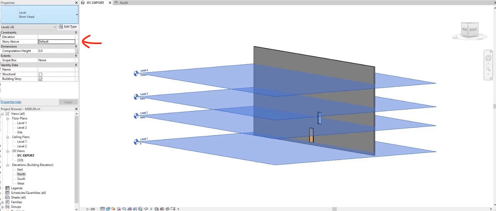
If walls were going through multiple levels we can choose to split them at each building story where the elements are split is defined using the level above property.
I mentioned about “Storey above” property in the second part of this series.
Include steel elements (numer 9) will export steel connection elements if selected.
File Header Information.. (number 10) and Project Address (number 11) allows general project information delivered with the IFC file to be customized.
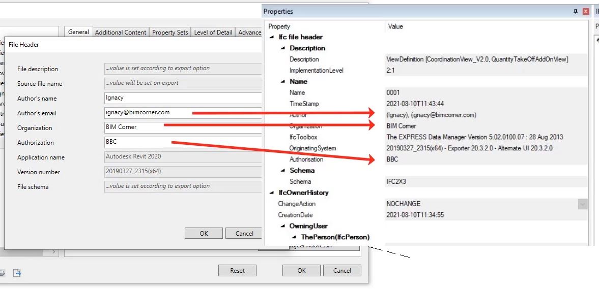
File header information allows us to add additional information to be specified as part of the ifc header. Once completed and exported is visible in the IFC file header.
Include steel elements (numer 9) will export steel connection elements if selected.
File Header Information.. (number 10) and Project Address (number 11) allows general project information delivered with the IFC file to be customized.
File header information allows us to add additional information to be specified as part of the ifc header. Once completed and exported is visible in the IFC file header.
Additional Content tab
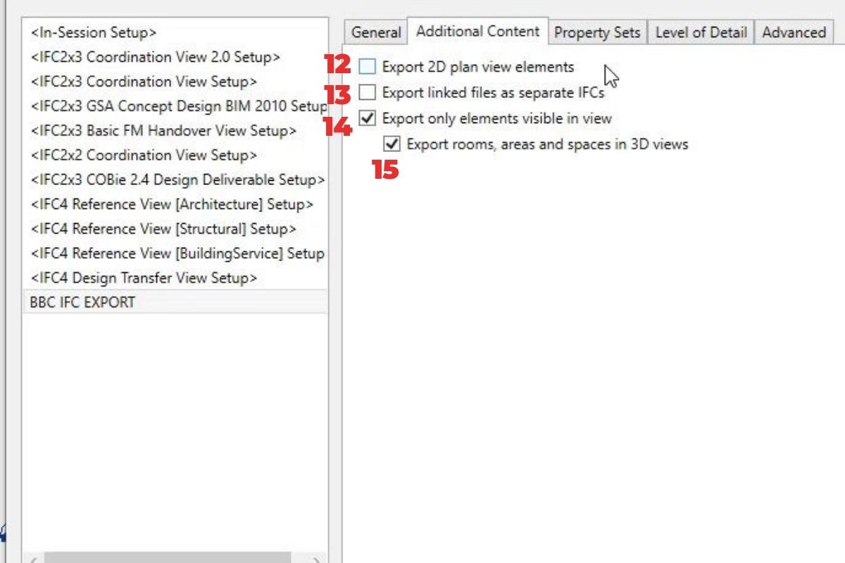
Let’s jump to the additional content tab. Here we have options to export 2D plan view elements (number 12). This option will export floor plans and room tags within the IFC for viewing.
What’s more, we can export linked files as separate IFC’s (number 13) so any linked files in this particular Revit model.
Additionally, we can export only elements visible in the current view (number 14) that is opened. I can also choose to export rooms, areas, and spaces from these 3D views (number 15). I use these options quite often.
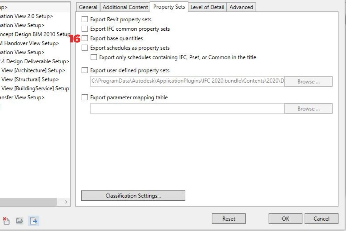
Property Sets tab
The one we didn’t mention is base quantities (number 16). This option provides base quantities as a basis for determining quantities and creating simulations.
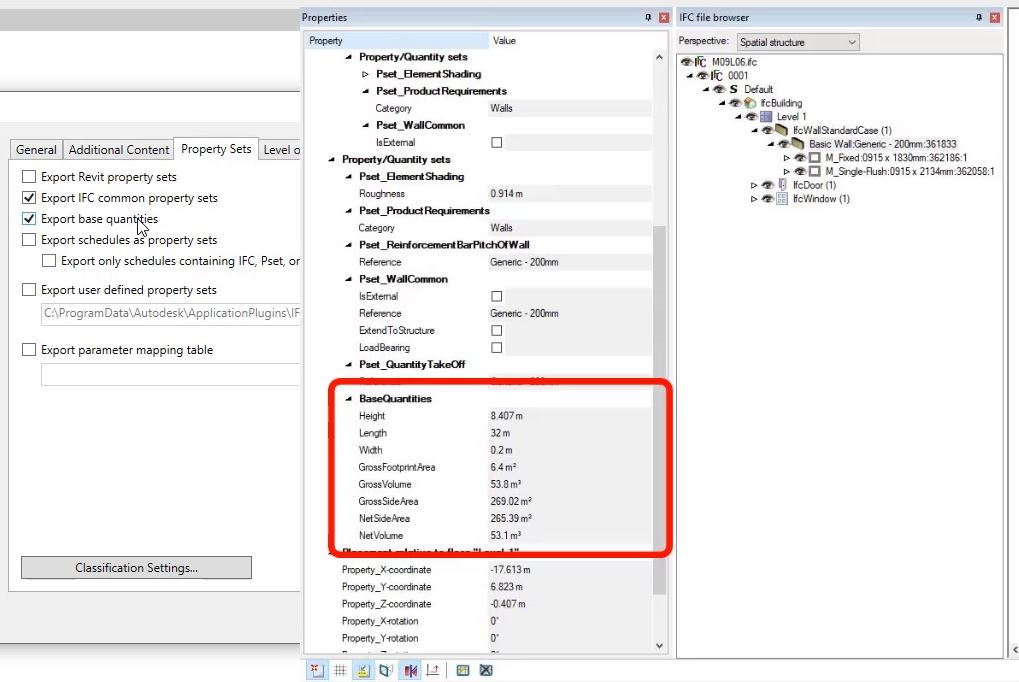
When we export a model, these properties are populated to IFC in a way, you see on the picture below.
The one we didn’t mention are base quantities (number 16). This option provides base quantities as a basis for determining quantities and creating simulations.
When we export a model, these properties are populated to IFC in a way, you see on the picture below.
Level of Detail tab
Under the level of detail tab, we have an option to specify the level of detail (number 17) for some element geometry. I can be set to extra low, low, medium, or high.
This option allows the control of the level of tessellation for some Revit elements. The main Revit elements affected by this control are: elbows, floors, pipe fittings, railings, ramp spaces, and stairs.
Having a greater level of detail will generally result in greater file size.
Components should be exported with a high level of geometric detail only if needed, as it can cause data bloat. The detail level “Low” is usually sufficient.
Advanced tab

In the Advanced tab we have a few options to choose from:
Export parts as building elements (number 18) – is relevant to IFC data exchange when working with partial elements in the construction of walls or floor slabs. Partial elements are exported as “IfcBuildingElementPart” by default. This allows individual parts to be assigned to a higher-level element within the IFC data model.

Allow the use of mixed solid model representation (number 19) – If checked this will allow for mixing of b-rep and extrusion geometries for an entity. This can result in smaller IFC files that are not strictly within the standard ifc model view definitions.
Use active view when creating geometry (number 20) – this option exports the geometry according to the view including the scope box if using a scope box. It was specially developed for building equipment elements such as cable routes and built-in parts whose model geometry differs from the represented geometry (like for example Cable Tray’s)

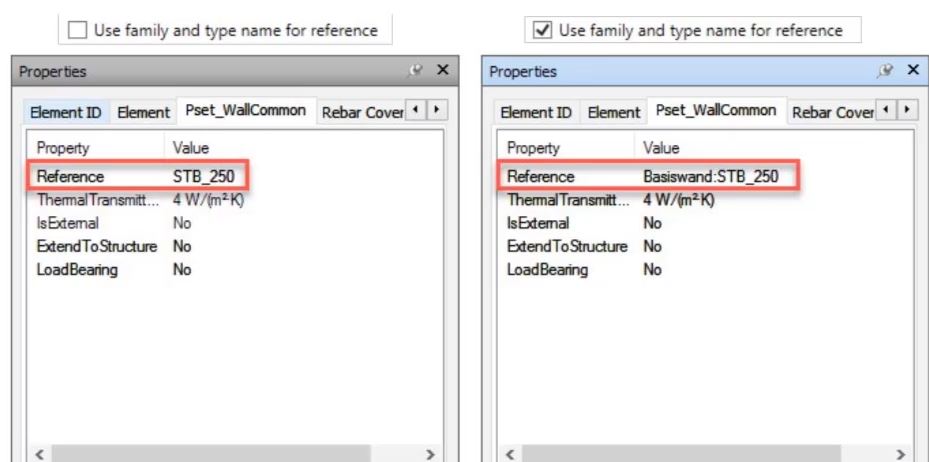
Use the family and type name for reference (number 21) – If this is checked then the family name and the type name will be used for the reference property. If not then just the type name will be used.
Use 2D room boundaries for room volume (number 22) – If checked, it will use a simplified approach to the calculation of room volumes based on extrusion of the 2d room boundary in the plan.
Include IFCSITE elevation in the site-local placement origin (number 23) – This will include Z-offset from the IFC local placement. This is important to ensure that all teams are using the correct setting for this as otherwise the IFC models may not be coordinated correctly in the Z plane. I recommend having this box ticked.
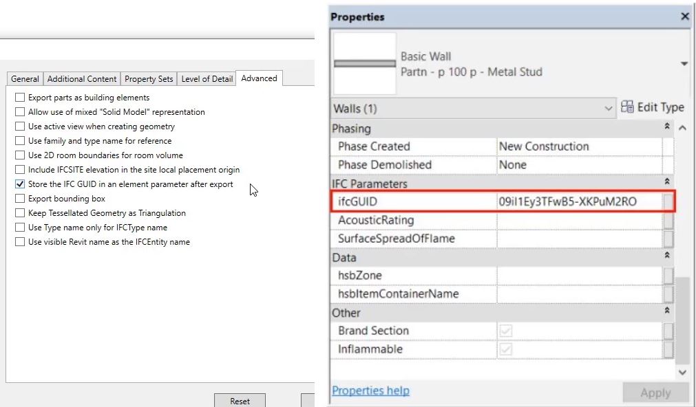
Store the ifc global unique identifier in an element parameter after export (number 24) – This will include the IFC GUID global unit identifier for the specific ifc element. It will save it back to the element to which it corresponds in Revit.
Export bounding box (number 25) – Every geometrical element can also be represented in a simplified manner using a bounding box – if this is checked it will export the bounding box representations of elements.
Keep Tessellated Geometry as Triangulation (number 26) – This option will not optimize b-wrap to be exported as ifc polygonal face set. In IFC4 Reference View export setup, this option may speed up export time for models that have large and complex geometries.
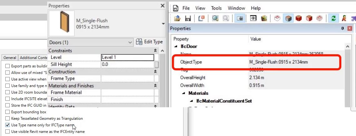
Use Type name only for IFCType name (number 27) – This will override the ifc object type name with the Revit type name
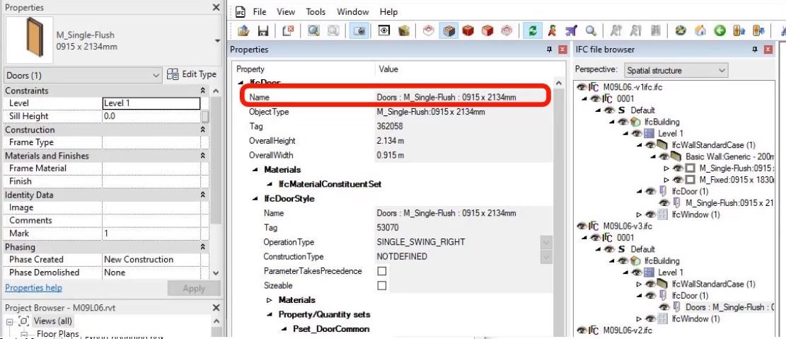
Use visible Revit name as the IFCEntity name (number 28) – This will concatenate the category family and type as the ifc occurrence name and not include the Revit element id.
To sum up
As you see IFC Exporter gives a lot of various options to choose from. I encourage you to test them on your own and check how your IFC files will be affected by each setting.
This was the final article about exporting IFC from Revit. I hope now you have a better understanding how IFC exporter works and you will be able to export IFC from Revit in a way that will suit your project needs.
!! Just as a final word. I explain the topic “IFC Export from Revit” in detail in my online course BBC – Become BIM Coordinator, which will be released on 22.02 February.
More than 170 lessons, more than 26h of video content full of BIM knowledge.
If you are interested, feel free to visit becomebimcoordinator.com website and join to the wish list. I will send you all details about this extensive online training.
Remember that if you find this article useful, and you think it might be interesting to one of your friends, please share it.
Take care, and see you in the next blog post.