

Façade drawings need floor levels, opening heights and relevant roof heights, presented consistently. When the model changes, those numbers have to change too.
I develop personal Revit tools with Codex, an AI coding agent, from drawing rules I use as a designer. This one places height annotations on façades.
The difficult part was defining what each number meant and how the command should behave after a change. I then tested the tool six times in Revit. Three tests met their criteria. Three were only partial, and they show the decisions I still have to make myself as the designer.
In this article you will see:
- How I defined where each number comes from
- How I set up tests that could not affect each other
- Why a correct measurement still did not produce an annotation
- Four checks you can apply to any Revit automation, written with AI or not
How I used Codex, and what I still decided myself
The saved development conversations record several practical problems. In August, I reported windows being selected from other façades, incorrect heights, problems with the reference zero and old annotations remaining after another run.
Those observations helped make the requirements more precise. They also remind me why a plausible drawing or a successful completion message cannot establish that an automation works correctly.
A measurement, its selection and its placement need separate checks.
Codex helped write and revise the tool, inspect its source and recorded development history, run the test session in Revit under my instructions, and prepare this article. It also helped create the separate measurement script.
The tests expose the decisions I still have to own as the designer:
- The reference level
- The meaning of an opening height
- The supported geometry
- The visibility rules
- What a rebuild may replace
Step 1: decide where each number comes from
The current tool uses the project elevation of a specifically named first-floor finished-floor level as its zero. It subtracts that value from each source elevation and prints metres to three decimal places.
A missing required level causes a refusal. The lowest project level is labelled as ground, which remains a project convention: a basement could make that description inappropriate.
In the test model, the finished-floor zero was −125 mm in project coordinates, and the lowest level was 335 mm below it.
For windows and doors, the tool reads the actual outline of the opening in the host wall, through a Revit API function that IFC export also uses. It does not substitute the family bounding box or a height parameter for that outline.
The host wall must meet the supported wall and viewing conditions. The tool also casts test rays to check whether something blocks the opening. If a ray hits something, the opening is skipped.
Roof heights come from the upper faces of standard Revit roofs with planar geometry and straight edges. A generated finish shell does not supply the roof elevation, and a lower slope edge on the upper surface does not establish a soffit underside.
How I tested the tool without one test affecting another
The tests used Revit 2025.1 and pyRevit 6.5.3, a free add-in for running your own Python scripts in Revit. An isolated, non-workshared copy of the model was opened with a neutral filename.
After the first command run, its result was saved as S1. Each later test started from a separate file copy of S1, so a changed window in one test could not affect another.
I checked that testing did not change the original model or the tool’s seven source files: their file fingerprints (hashes) stayed the same. In the tool, I ran only the façade formatting stage. Test changes to model geometry and the independent measurements were carried out using a separate Revit API script. See Fig. 1.

That script gave a second, independent way to measure. It read the inner edges of the wall openings directly from the wall geometry, instead of using the tool’s own routine.
Roof checks read points on the upper faces of the roofs. The record also captured annotation types, text, coordinates and stored element IDs.
These checks ran inside Revit. Screenshots, view exports and the complete diagnostic output were saved alongside the measurements.
The test model had two unresolved links and an inactive view crop, so these tests do not cover linked geometry or active crop behaviour.
The six tests at a glance:
| Test | What I changed | Result |
|---|---|---|
| T1 First run | Nothing; old annotations were already present | Partial: 7 correct numbers, +0.600 m omitted for space, no door accepted |
| T2 Rerun | Nothing | Met: the same 7 numbers, no duplicates |
| T3 Taller window | One window made 200 mm taller | Partial: +2.600 m read correctly, no annotation placed |
| T4 Close heights | One of two windows with the same top made 100 mm taller | Partial: +2.500 m read correctly, no annotation placed |
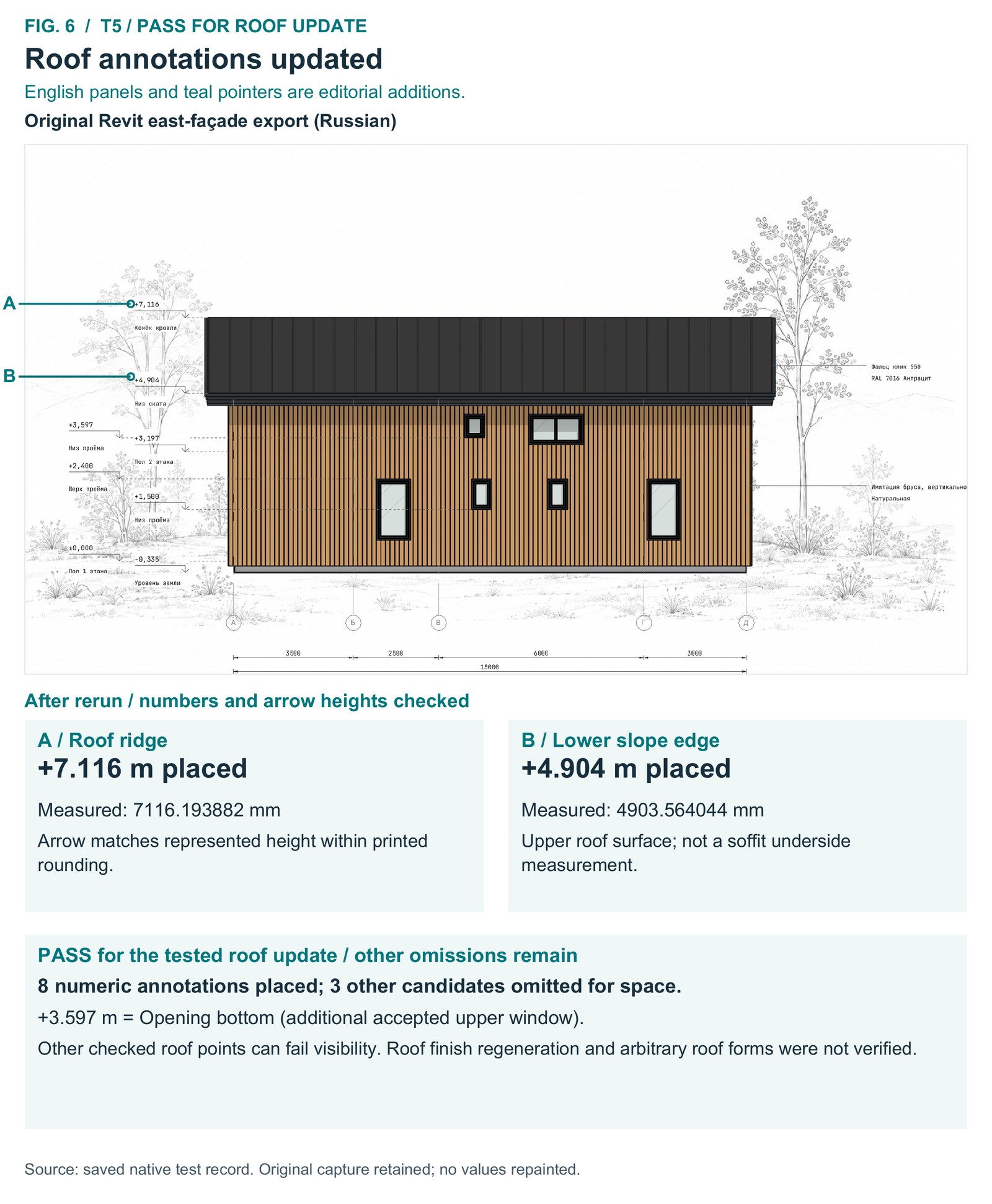
| T5 Roof raised | One roof raised by 300 mm | Met: +4.904 and +7.116 m, arrows match |
| T6 Symbol moved | The +2.400 m symbol moved 1000 mm sideways | Met: symbol rebuilt, the manual move was lost |
T1 and T2: first run and an unchanged rerun
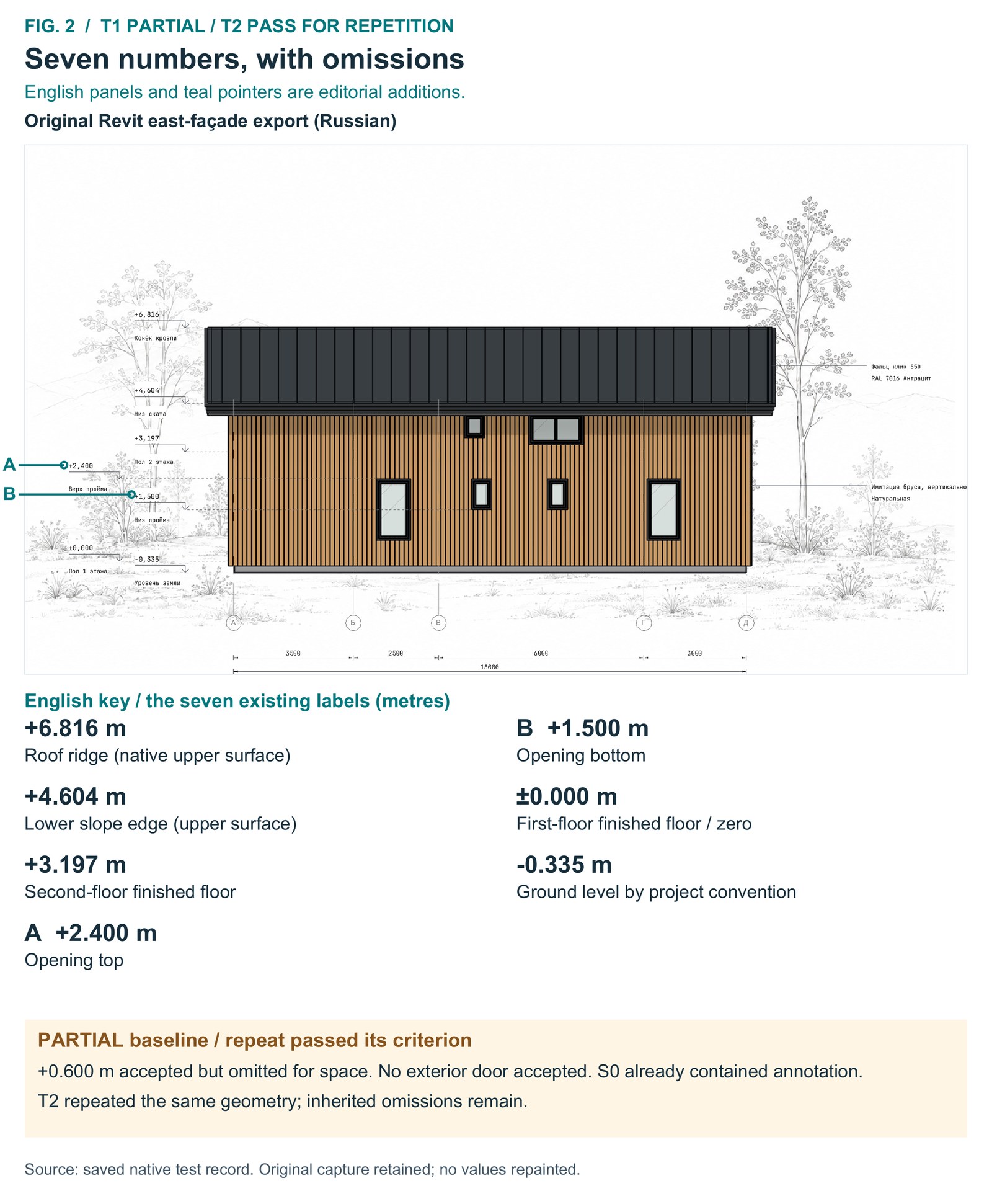
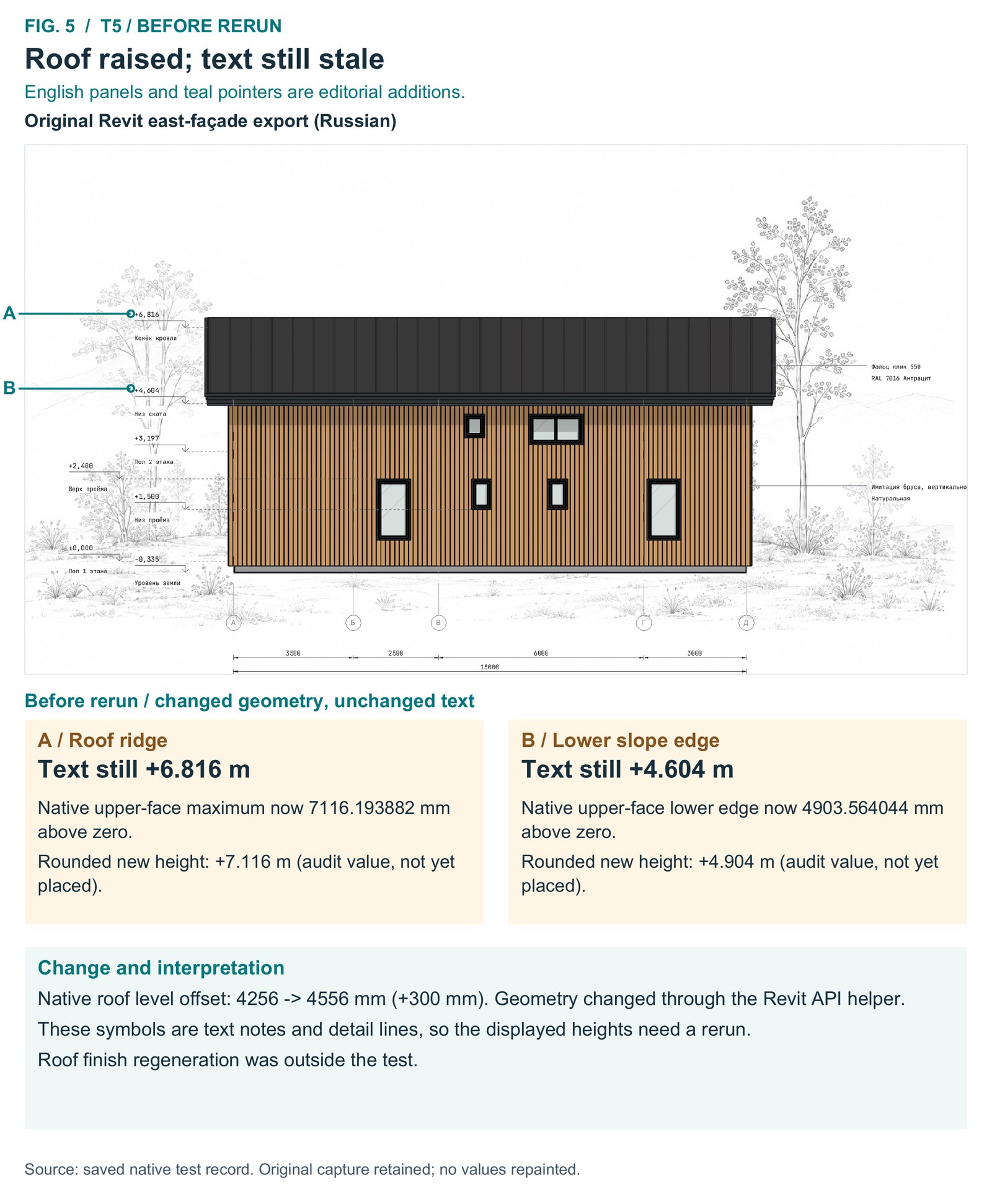
The first run produced seven numeric annotations on the east façade, which I used as the control, at scale 1:82. They included an opening top at +2.400 m, an opening bottom at +1.500 m, and roof values of +4.604 and +6.816 m.
The roof values corresponded to independently measured heights of 4.603564 and 6.816194 m above the finished-floor zero. All seven arrow tips matched their represented heights within the rounding tolerance.
However, the accepted +0.600 m opening-bottom candidate was omitted for lack of layout space, and no exterior door candidate was accepted on the tested façades.
Existing annotations were already present before the run, so this was a rebuild, not evidence of creation from a clean model.
Next, I ran the command again without changing the model. It removed the annotations it had drawn before and drew them again: the same seven numbers in the same positions. Only the Revit element IDs were new.
The tool keeps a list of the elements it created in each view. The list held 54 entries before and after the rerun. None of the old elements were left behind, and the total element count did not grow. In practice, running the command twice does not pile up duplicates.
That supports repeatability for this baseline. It does not make the inherited omissions disappear or prove that every manual annotation is protected. See Fig. 2.
T3 and T4: correct heights, but no new annotation
The window change exposed a dependency between geometry and visibility.
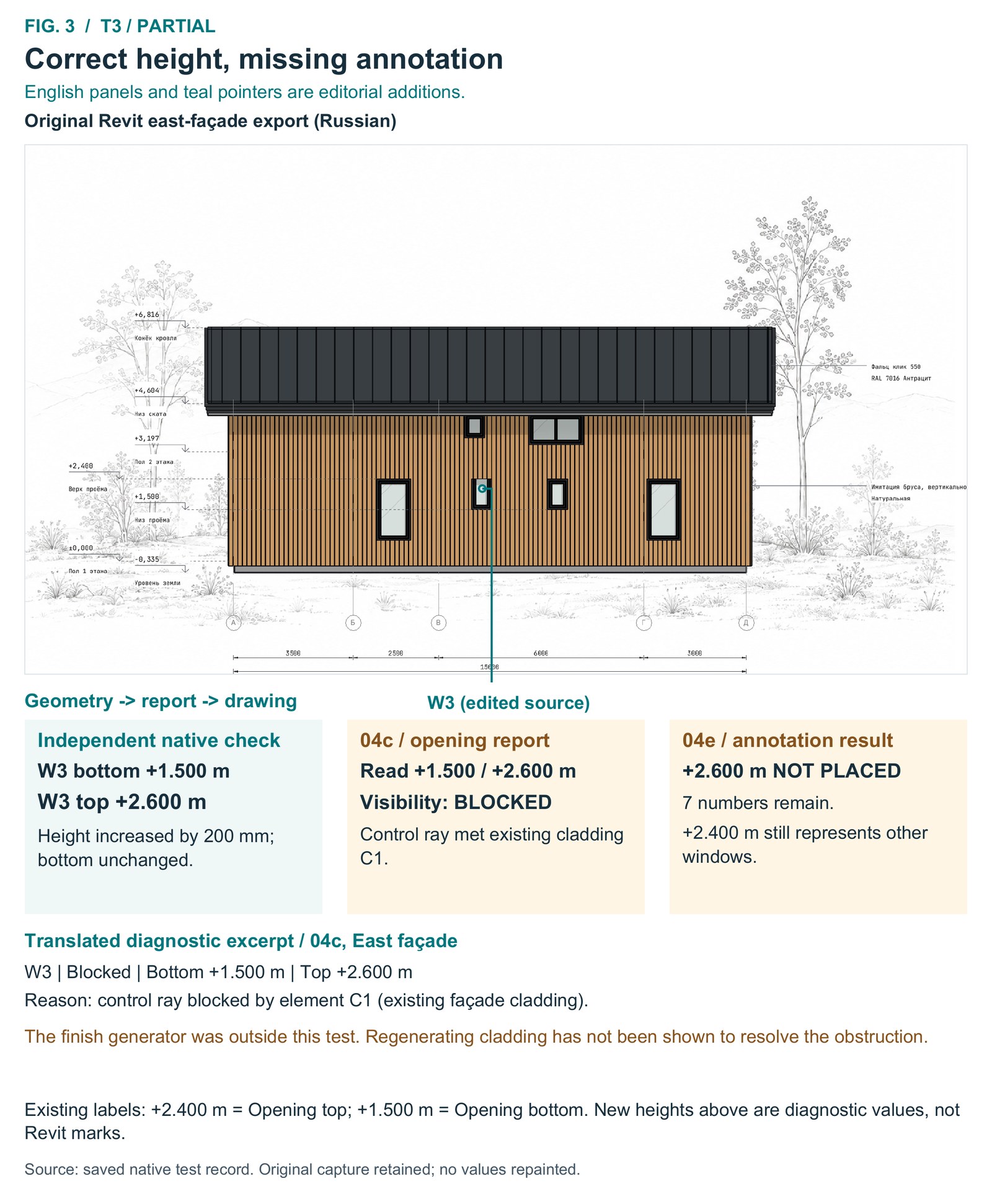
In T3, one window was made 200 mm taller. The independent check confirmed that its opening bottom stayed at +1.500 m while its top moved from +2.400 to +2.600 m.
The command read those heights correctly. But its visibility check rejected the changed opening, because a test ray hit existing generated façade cladding. No +2.600 m annotation was placed.
The remaining +2.400 m number still represented other windows. The cladding generator was outside this test’s scope, so this result does not prove that regenerating the cladding would solve the problem. See Fig. 3.
T4 had a similar limit.
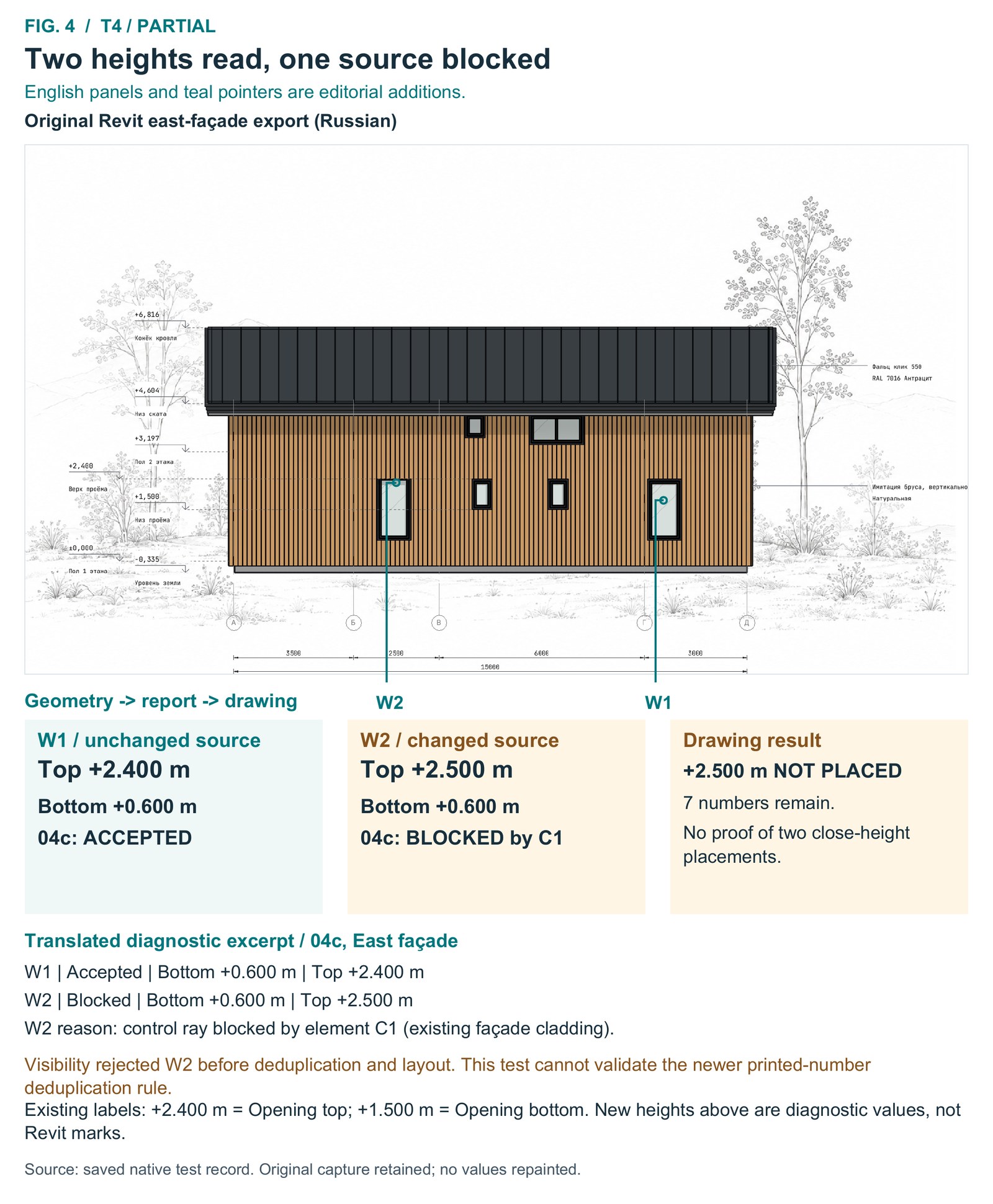
Two window openings initially shared a top at +2.400 m. Making one 100 mm taller, with its opening bottom unchanged at +0.600 m, created a real top at +2.500 m, while the other remained unchanged.
Both heights appeared correctly in the diagnostic table, but the changed window was again rejected because of the cladding. The drawing therefore did not show two separate close-height annotations.
An older version of the code merged heights closer than 180 mm. The current rule merges only heights that would print as the same number. This test cannot confirm placement under the new rule, because visibility rejected one window first. See Fig. 4.
T5: the roof moved and the numbers followed
The roof change provided a successful update example.
Raising one roof by 300 mm through its level offset changed the independently measured lower edge and maximum height by exactly that amount.
Before rerunning, the text still showed +4.604 and +6.816 m. After the command, it showed +4.904 and +7.116 m, with matching arrow heights.
The façade now had eight numeric annotations; three other candidates were omitted for space.
This confirms the tested roof update, while full roof finish regeneration and arbitrary roof forms remain outside the evidence. See Fig. 5, Fig. 6.
T6: manual edits to generated symbols are lost
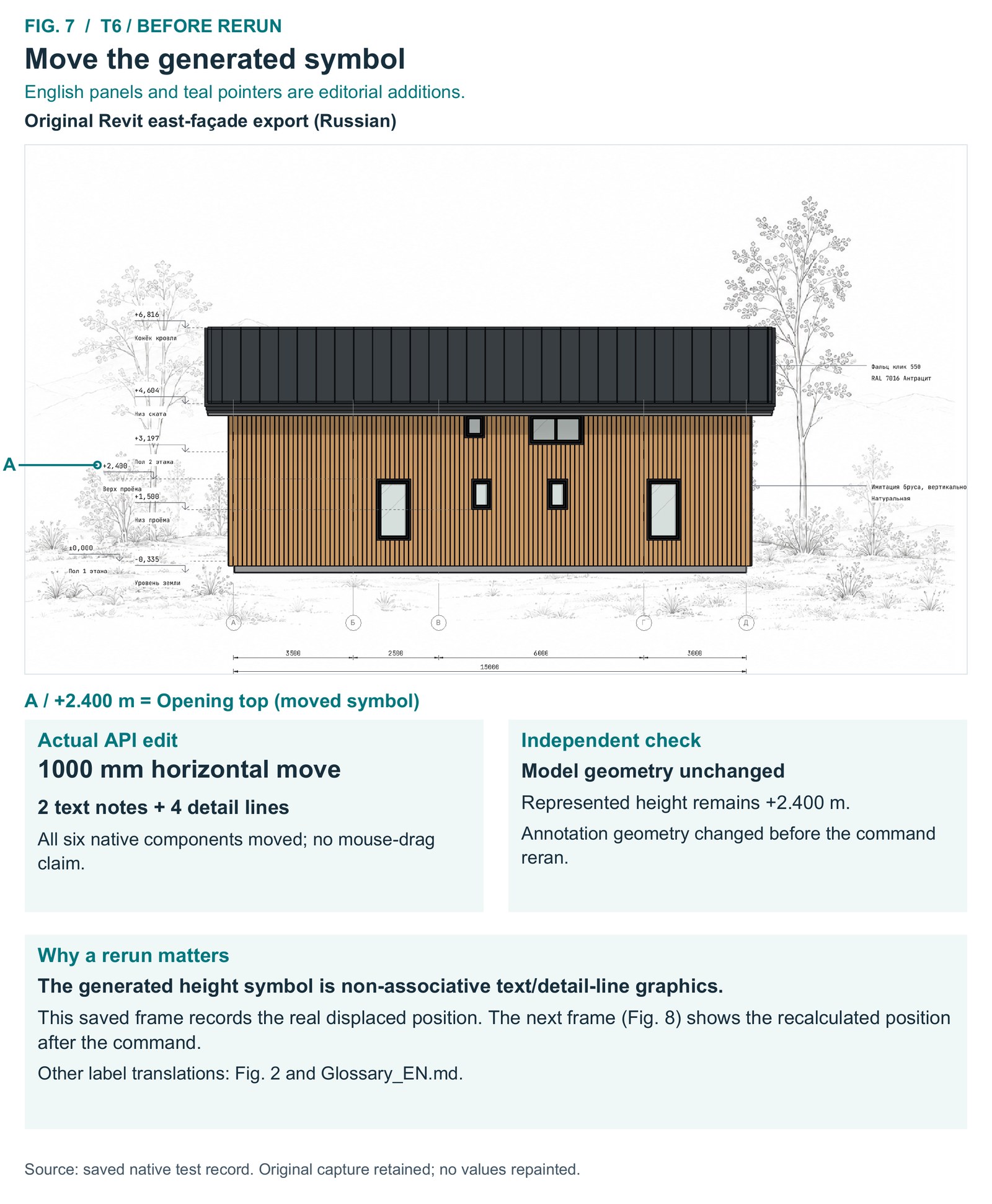
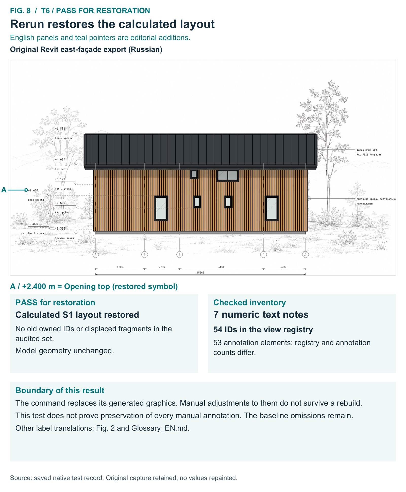
The symbols explain why rerunning matters. Each height symbol consists of two text notes and four detail lines, with extra guide graphics where supported. They are not Revit Spot Elevations, which update automatically with the model. They change only when you rerun the command.
In the final test, the separate script moved all six parts of the +2.400 m symbol 1000 mm sideways, without changing the model.
Rerunning removed the old elements created by the tool and restored the calculated layout. No displaced fragments were left behind.
A designer’s adjustment to generated graphics therefore does not survive this rebuild. See Fig. 7, Fig. 8.
Warning: the command changes more than height symbols
The command reaches further than one symbol. Its selected stage also processes sections, legends, backgrounds, grid ends and other architectural view layouts.
The first run’s report also recorded removal of one 3D viewport from the title sheet.
Warning: the code contains façade cleanup rules that can delete standard Revit Spot Elevations, including ones placed by hand.
My test façades had no Spot Elevations before or after, so I did not see it happen. That risk is a finding from the code, not a measured loss. If you build a similar tool, check what its cleanup step is allowed to delete.
What to take into your own Revit automation
Three tests met their criteria: the unchanged rerun, the roof update and the rebuilt symbol.
Three were partial: the first run and both window tests.
The command reported no errors, but exclusions and layout omissions still affected the result. I have no measured time saving or broad reliability figure to attach to this case.
What the tests give me is a clearer way of working. Here are four checks you can apply to your own tool:
- Define the geometric source. Decide which element and which face each number comes from, for example the opening in the wall, not the family bounding box.
- Read the diagnostics. A correct measurement can still be rejected, as in T3 and T4.
- Rerun after changes. The annotations are plain text and lines, so they do not update by themselves.
- Review the affected drawings. The command touches other views too, and manual adjustments are overwritten.
Personal automation becomes useful when those decisions are explicit enough to test and its limits remain visible in the drawing review.
If you want to build your own Revit tool with AI, start with the rules, not the code. Test one change at a time on a copy of the model, and check the drawing, not only the success message.
This post was written by BIM Corner’s Guest Author, Andrey Kechin.