
The idea of building directly using models is steadily on the rise, and more projects are taking this approach. Some time ago, I wrote about what is required from such a process and its benefits and challenges. One of the most important topics that arise is the setup of rigid and smooth processes and software flow.
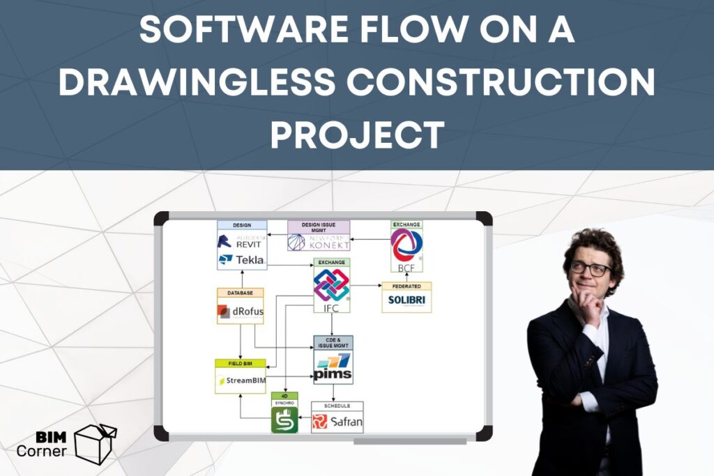
In this entry, I want to focus on the general software setup, using the project I’m involved in, New University Hospital in Stavanger, as an example. What software do we use in each project phase? What is the flow? Answer these and more questions below.
Table of Contents
Digitalization goals
To discuss the set-up we have to first revisit the project digitalisation goals. The construction management team’s role was to enhance the project technology to meet the client’s requirements and to allow for model-based building. We could divide them into three categories:
- Eliminate the creation of traditional drawings and create models that can be used as construction documentation.
Simply speaking it is discarding drawings and using models. Although the reality isn’t simple. We had to set up the whole construction site and procure and define software flow that could be used directly on-site by workers.
The project had to define information requirements for the models and accordingly feed them with data needed for workers and surveyors to perform on-site activities and measurements. - Collaboration between stakeholders should be digitised regardless of the project phase and personnel location.
This required setting up a cloud-based project management and collaboration hub for all project stakeholders (building owners, designers, contractors, suppliers, and end-users). Nonetheless, it is not only about the tool – the whole other story is establishing and following up task management and communication processes in the organization for well over 300 white-collar workers. - Each piece of information must be maintained only in one place and managed effectively through digital collaboration.
Tricky one. In the AEC industry, we are used to creating spreadsheets, registers, and matrices. We export data from one source, develop it and use it as long as it is suitable and then leave. Or we manage multiple parallel registers. You know what I am talking about? Room planners have their room registers, architects have theirs, and MEP engineers have theirs. Data gets duplicated and changed and initially, the same registers are drifting further and further apart from one another.This requirement puts an end to this. Each piece of information is to have only one place that is a master for data and it can feed other sources that are master for other data. In other words, we are creating a huge relational database with interconnected tables. And since no software can do everything, we have to decide beforehand on the workflow and which program manages which type of data.
In conclusion, this requirement creates possibilities—we save time by not maintaining the same information in many places. On the other hand, the project must set up new workflows and data exchange processes and reevaluate well-established design and communication routines.
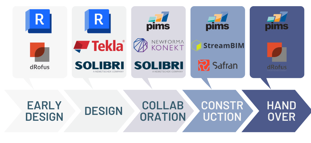
Software throughout project phases
Setting up workflow, we had to take into consideration that the particular software use is changing through the project lifecycle. In the end, we have chosen a set of tools that worked OK with each other as a backbone.
From that point, we added some programs that supported given tasks (e.g. door management, acoustic calculations) and the prime requirement was that they could cooperate with the bundle we already use.
Properties purposes
Before we jump into the description of which software was doing what and how they are connected, let us revisit one more time object properties.
In every project we create, model and manage properties for different project purposes. Afterwards, this defines which data flows where and how the software collaborates. I would divide them as follows:
- Design input – data setting the requirements for the project. Designers need it to begin and continue the modelling process. It flows as an input to modelling software. Example properties:
- Departments
- Programmed area
- Fresh air quantity
- Security systems requirements
- Design – properties needed to be exchanged between design teams. MEP engineers need input from Structural Engineers and they need it from Architects. And the other way around. Examples:
- Columns grid
- Designed room boundaries
- Wall types
- Ceiling height
- Collaboration and project management – information to allow project management and collaboration between stakeholders responsible for different deliveries – scheduling, tasks, control, testing, etc.
- Control area – to know what place are we referring to
- Responsibility – to know who are we referring to.
- Model Maturity Index / LOD – what is the stage of development of an object, what can we use it for
- Construction – properties needed for contractors to do their job on-site using models. Examples:
- Door schedules
- Pipes dimensions
- Power type, voltage
- Handover – information for the end user to be able to manage the facility. Managers have to know what was in the end installed on the construction site, how to operate it and what are the maintenance routines. These data are often both PDFs as well product properties input in the object database. Examples:
- Product manuals
- Function tests protocols
- Guarantee conditions
By understanding these purposes we can manage information flow between different software. Another data set should be exchanged when we send the design between parties another for the construction and yet another when preparing for the handover to the Facility Management. This goes hand in hand with IFC export purposes, but goes beyond that – a lot of data is exchanged incorporating databases or inside one software but different teams.
Workflow between software
Design input
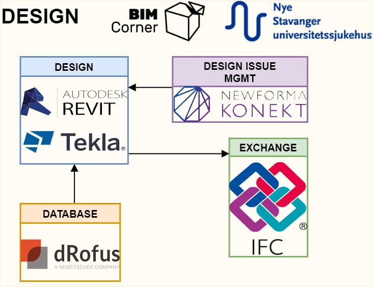
Design
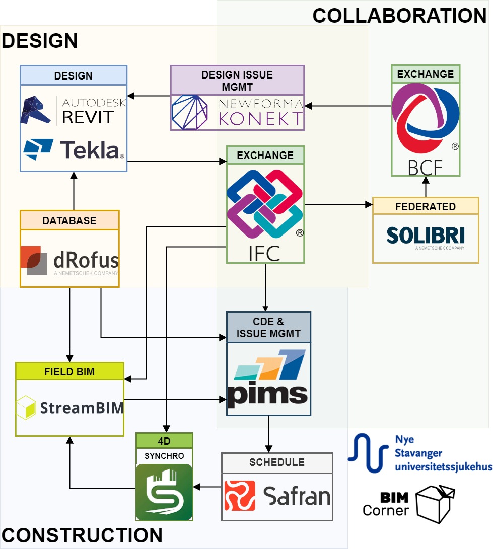
Then came designers and began to work in Revit and Tekla. They collect relevant data from the dRofus database to answer the requirements.
Every Friday there is an automatic IFC export for all models and during the weekend every platform is fed with fresh models.
Models are federated in Solibri. In the design process, the team uses it for quality assurance and clash detection, data control and information take-off. Both internally within the design team and for communication with the Building Owner.
For issue management internally, the design team uses a BCF server called BIM Track (now Newforma Connect).
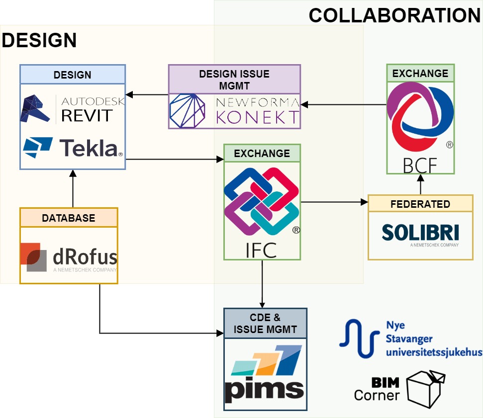
Collaboration
For issue management outside of the design team, we use Pims platform, which is the project’s main hub and every project stakeholder is contractually bound to use this software as a communication and task management platform.
Pims is our main tool to collaborate and store data. It is basically an enormous database with different modules that can be cross-referenced. Originating from the oil industry, it has been adapted to the needs of the construction market. The project uses it as:
- CDE
- Issue management and collaboration
- M&O documents repository (Maintenance and Operation)
- Quality control checklists for contractors
- Model data repository (we import all IFC to their database, and they can extract pure data from properties)
- Activity plan and register for workers on-site (using “wagons” from Lean principles)
- Timetable meeting – digital board with daily tasks for each construction team
- And more
Using one software for so many tasks has both pros and cons. On one hand, you have to learn only one program and all modules work similarly. On the other hand – many of the modules are better solved by separate platforms. Plus if everything has to go to Pims, then every software should cooperate with them. And here is the big issue on both sides – software vendors do not necessarily want to cooperate which influences the project’s workflow.
Construction
As a construction site software, we decided to use StreamBIM as it was the best solution on the market then. What made us make this decision?
- Dedicated application for touch screens – every single worker has it nowadays
- Efficient dimensioning and the ability to annotate elements
- Simplicity of navigation and easy preview of the floor plan
- Easy to create cross-sections.
The workflow for the construction site and combining schedules with models is as follows:
- From Pims, IFC files are sent to StreamBIM every Monday
- Schedules are made in the Safran Project which are also combined with data from Pims into a single activities register available for site managers and foremen.
- We combine IFC models with schedules in Synchro for schedule visualizations, so-called 4D. To be honest, we haven’t utilised this feature much.
On the project, we use BIM Stations that allow workers to view models regardless of the weather, wifi accessibility or battery issues. As a backup solution to StreamBIM – if the network is down, free Solibri Anywhere is installed on every BIM Station. It is hopeless for dimensioning and orientation inside the building, but has an undisputable advantage – works offline on files downloaded to the hard drive. This saved us many times.
Handover
When we reach handover the software flow is replaced by the data and documentation gathering. We have to combine basic PDFs, drawings and schedules with IFC models and project data.
For that we once again use Pims – since we already have each IFC object translated as a record in the database, we can combine them into datasets and connect relevant documents.
Workflow for collection of the MOM documentation:
- Imported IFC files are parsed and translated into database records by Pims
- Objects are combined into bigger datasets depending on their common features and documentation requirements
- A separate module in Pims is used to distribute those requirements to contractors to upload specified documentation types on the objects
- The ready database is handed over to facility managers together with training sessions
Summary
In this entry I merely touched the surface of integrating different software into one well-oiled cogs that performs tasks meant for them.
One thing is to choose the correct software bundle, but a whole different, and much more important topic, is to set-up the data flow between them, so that the information is really managed in one place and every program does only the job it was meant to do.
This is the topic I want to discuss the next time here on the BIM Corner blog. Stay tuned!