

In today’s world of engineering and architecture, effective data exchange plays a crucial role, facilitated in part by the Industry Foundation Classes (IFC) standard.
Working with IFC 4.3 and its implementation in Trimble Quadri software has allowed me to identify key elements that a well-exported IFC file should contain.
In this article, I will attempt to describe these elements and concepts that are essential for a comprehensive and reliable data exchange between different programs and designers. I will discuss both the technical aspects of the IFC file structure and concepts related to interoperability, readability, and data consistency, providing practical examples for better understanding.
I hope that this article will be inspiring and useful for those interested in IFC and project data exchange.
NOTE: This article is divided into two parts.
Welcome to the first part of the article.
- All you need to know about IFC 4.3 for infrastructure
- IFC 4.3 in road projects – case study
- Relations I used to create IFC 4.3 for infrastructure
- Spatial Breakdown Structure in IFC 4.3
- IFC 4.3 on construction site
- Webinar about IFC 4.3
- Ticket to openBIM
- Export to IFC 4.3
- The Key Changes in IFC Schema Shaping OpenBIM for Infrastructure
- Transferring from Civil 3D to Quadri and Exporting to IFC 4.3
- Five Effective Tools for BIM Data Quality Assurance
- Properties in IFC
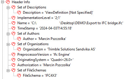
Header
The header of an IFC file is important in determining the basic characteristics of the document. It contains a series of essential pieces of information that allow for a quick understanding of its content. From the header, we can read the file name, saved path, creation date, authorship, and affiliation with a specific organization. Additionally, the header reveals information about the software used and the file’s generator.
One of the most significant elements that can be gleaned from the header is the purpose for which the file was generated. This is determined by the Model View Definition (MVD) and the IFC format that was applied. It’s worth noting that understanding these details is essential for properly interpreting the content of the file and its application in the context of a specific project.
In practice, sometimes we may encounter difficulties opening a file, especially if the application doesn’t support a specific IFC format, such as IFC 4x3_ADD2. In such situations, one workaround is to employ a certain trick that sometimes yields desired results. This involves modifying the format in the header, for example, changing from “IFC 4x3_ADD2” to the standard “4×3” format. Although this method doesn’t always work, it can be helpful at times, especially when the file contains basic objects and parameters. However, it’s important to remember that this is a temporary solution and doesn’t guarantee full compatibility with every application.
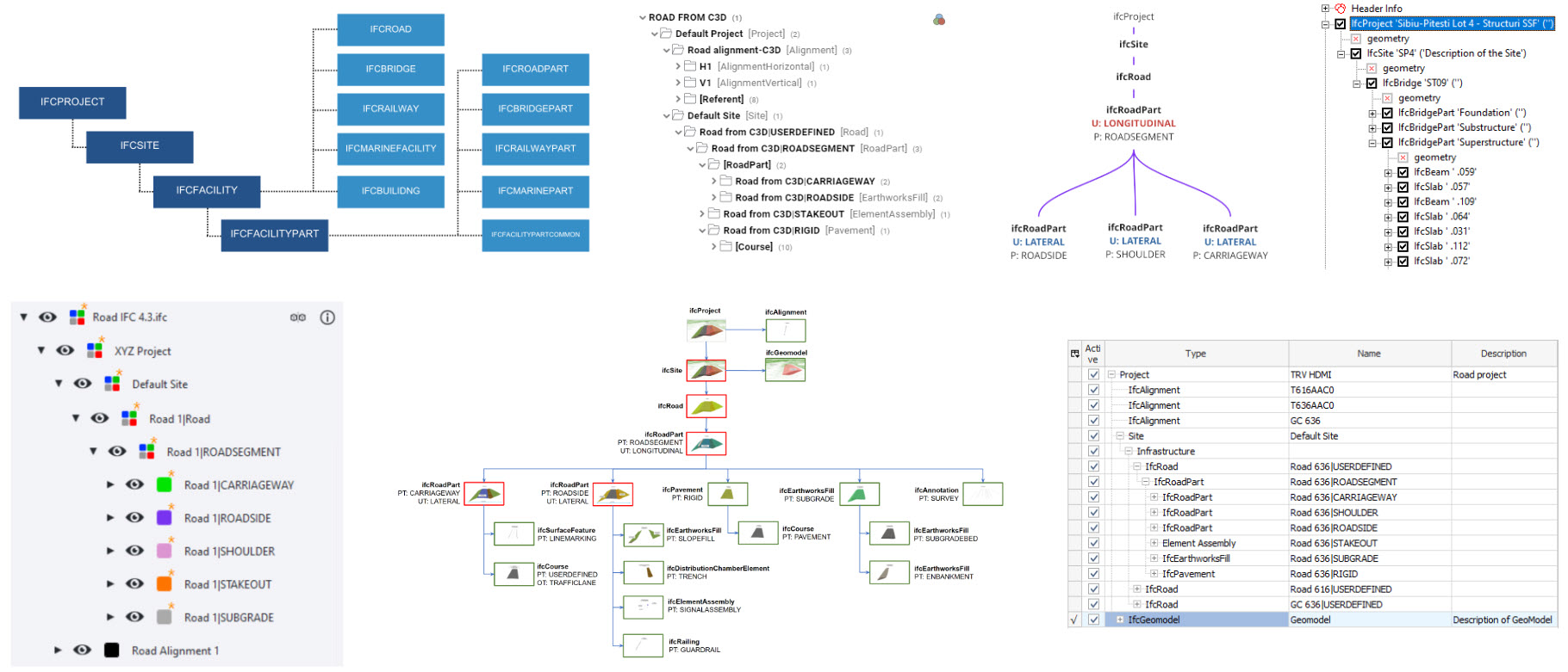
Spatial Breakdown Structure
For an IFC file to be well-defined, it must contain a spatial breakdown structure. This structure refers to the division of the project into smaller areas according to spatial layout, facilitating data management and analysis. Although there are other methods of decomposing projects, spatial structure predominates in most industries and project tasks. This makes it the primary schema for construction projects and an essential element for effective data exchange.
In the IFC file structure, a key element is the ifcProject object, which defines the context of the entire project. It contains information about the units used in the project and may include data about the coordinate system. Another essential element is ifcSite, which provides additional information about the construction area. Subsequent levels of the structure are represented by specific domains such as ifcBuilding, ifcRoad, ifcRailway, or ifcMarineFacility, which specify the characteristics of individual buildings or objects.
A well-defined IFC file structure is essential for proper data interpretation and can bring many benefits in the IFC file analysis process. Therefore, it’s important to ensure that the spatial structure is clear and aligned with the project requirements.
For more information on the significance and implementation of spatial structure, you can read the article available [here].
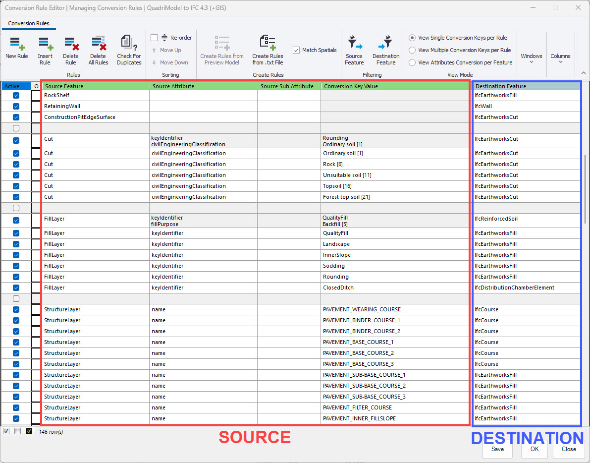
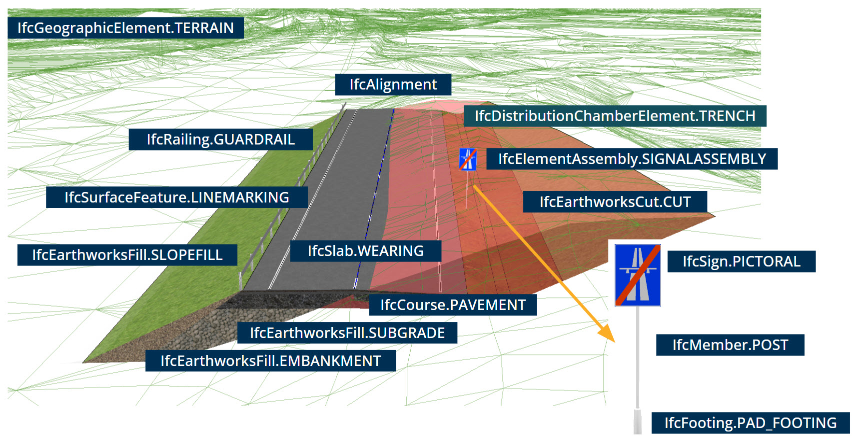
Objects
In the context of an IFC file, it is important to accurately assign classes describing both existing and planned physical elements. Unlike simple proxy objects, precise mapping to the appropriate classes brings greater added value.
IFC classes are created to facilitate model interpretation, ensuring universality, flexibility, and ease of working with data.
Though it requires some time investment, well-considered mapping between software and the IFC file significantly improves the quality of exported data. Thoughtful matching of classes to model elements can substantially contribute to the effective interpretation of data by various stakeholders involved in the design process and facilitate their further utilization.
Attributes
Classes should be carefully described by assigning them appropriate attributes. Although the type and number of attributes may vary between classes, I believe that each object from the IfcProduct group should be equipped with at least the following attributes: Name, Description, PredefinedType, and ObjectType, which significantly facilitates their more accurate identification.
It is also extremely important to consider certain mechanisms, for example, when the value of the PredefinedType attribute takes the value USERDEFINED, then the value of ObjectType should be utilized.
To maintain consistency, it is crucial to determine the value of the ObjectType attribute in advance. This is particularly important because this attribute allows the use of String type values, which can lead to potential issues. Therefore, it is extremely important to appropriately define the ObjectType at the preliminary stage of the project.
It is also worth remembering additional attributes, such as Tag and UsageType. These two attributes are particularly important when describing spatial objects or others belonging to the IfcElement group. Including them allows for an even more detailed description and identification of objects in the model.
Geometric representation
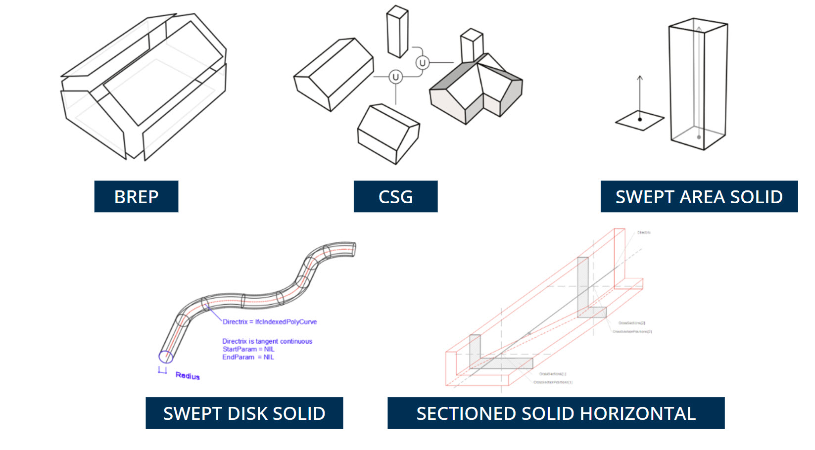
When exploring IFC classes, we encounter a variety of geometric representations that play a significant role in this domain. These representations include points, curves, surfaces, and solids.
It’s important to understand that each of these types can be described in different ways. For instance, when it comes to solids, there are several techniques like “swept solid,” “solid model,” “advancedBrep,” or “CSG.” However, it’s crucial to note that not all software supports all types of geometry.
One commonly used and reliable option for solid representations is Brep, which stands for “Boundary Representation.” This method involves precisely defining the boundaries of a three-dimensional shape to describe it. In a Brep, the solid is made up of interconnected surface elements that define the boundary between internal and external points.
Therefore, it’s beneficial at the outset of a project to assess which geometries are supported by the software used for creating models and whether the program used to analyze the object can interpret this geometry.
An example of a geometry that might pose challenges for IFC file viewers is “SectionedSolidHorizontal.”
Summary of part one
In the first part of the article, I thoroughly discussed the key aspects to consider in an IFC file. I focused on the significance of the header, spatial structure, objects, attributes, and the method of geometric representation.
These elements form the essential foundation for effective data exchange between different programs and among designers.
In the next part, I will continue this topic. I invite you to keep reading, where I will present further aspects that an IFC file should encompass.