Spatial Breakdown Structure (SBS) is a method of organizing and breaking down a project into smaller, manageable components. Spatial hierarchy used in IFC establishes a system for placing physical elements within a construction or infrastructure project according to their location in space. About Spatial Breakdown Structure I mentioned a bit in this entry: LINK
If you are interested in the topic of IFC 4.3, don’t forget to check out other articles dedicated to this subject on our blog.
In this article, we discuss the purpose and benefits of using SBS, as well as how it applies to infrastructure projects.
Model representing Road and WS domain:
NOTE: Discussed IFC 4.3 model was created in the Trimble Quadri software. The model is provided for educational purposes. At this point, it is possible to create a IFC 4.3 model in the development environment to which I have access as a Trimble employee. If you want to know more about the Trimble Quadri product, write directly to me on Linkedin.
Spatial Breakdown Structure and Work Breakdown Structure
The IFC system uses a spatial hierarchy to organize and position physical entities within a construction and infrastructure project. This includes the ability to link specific features, such as elements of roads, railroads, drains, or light poles, with a named section of the infrastructure for improved asset management and organization.
It is important to note that SBS differs from other types of breakdown structures, such as Work Breakdown Structure (WBS), in that it focuses on the physical location or geographic area of the project, rather than on the work itself. While WBS breaks down the project into smaller, manageable chunks based on the work that needs to be done. SBS breaks down the project into smaller, manageable chunks based on location. This allows teams to focus on specific geographic areas and to plan and prepare for issues related to working in those areas.
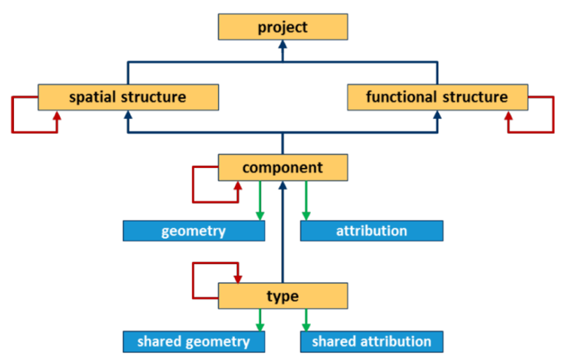
(1) Division of the project in IFC schema (source: buildingSMART International)
Spatial Breakdown Structure and IFC
In construction and engineering, it is common to break down a building into smaller, manageable parts, such as the individual floors and rooms, for better organization and management. This process is known as spatial decomposition. A typical division in building projects is as follows
Site
Building
Storey
Space
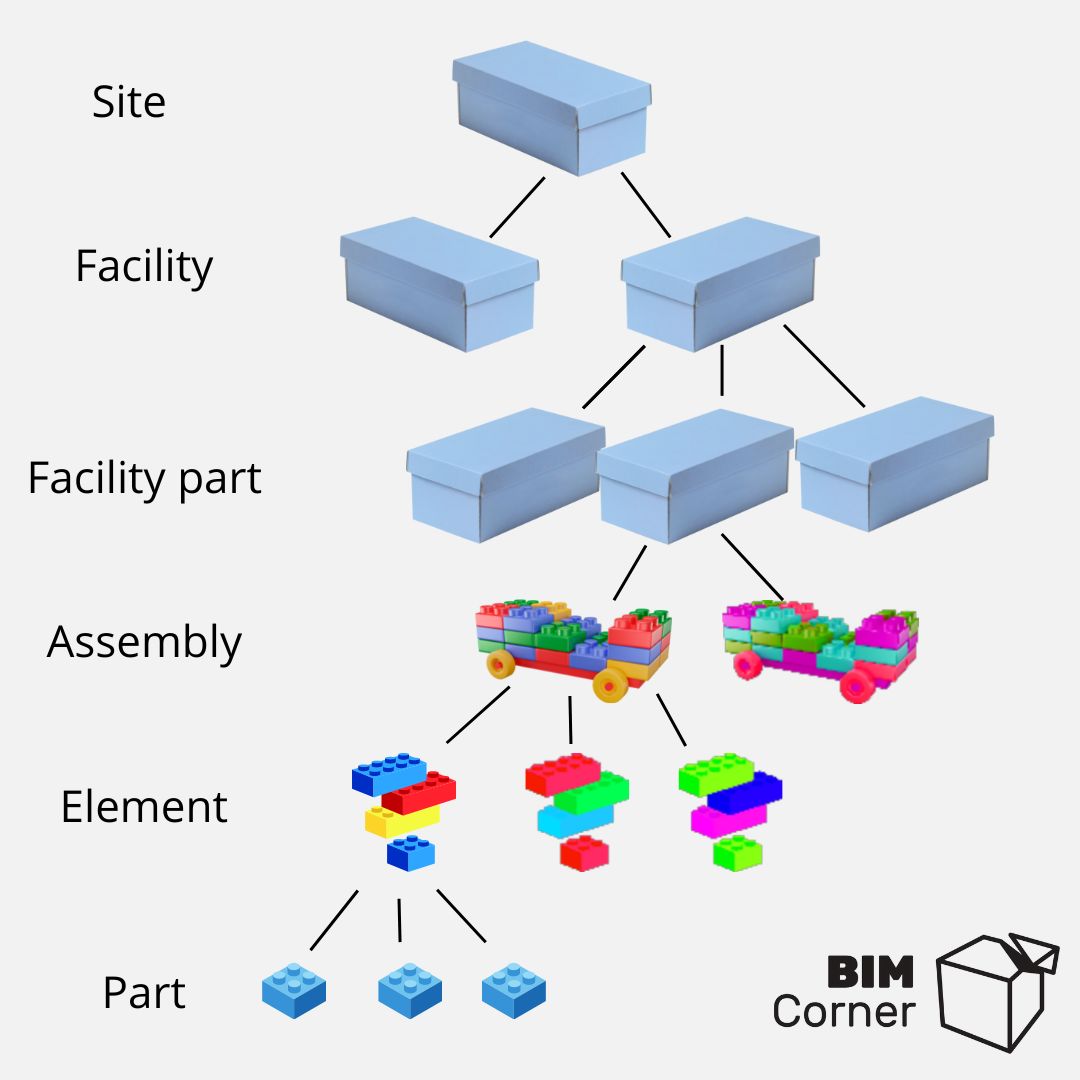
In general, spatial structure in IFC is the breakdown of a site into facilities and its parts. Further assemblies and their elements are connected to particular silos. Elements on the lowest level of hierarchy inherits attributes from the top.
(2) Decomposition of the project in IFC schema
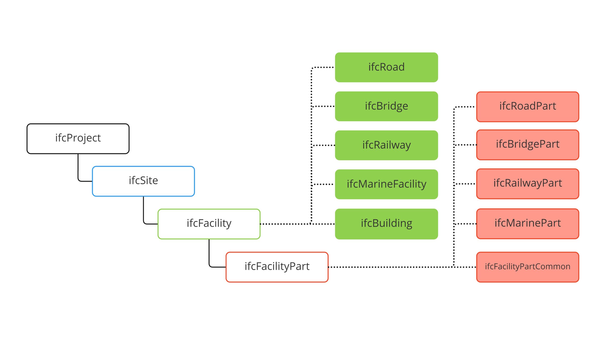
With the release of IFC 4.3, we have the ability to split built assets using new spatial objects.
We can better describe/divide objects such as: road, bridge, railway, marine facility.
(3) New entities within spatial decomposition of the project
Decomposition of the road project
The biggest difference between a building and a road is the area that these two assets occupy. Linear structures can be kilometers long, while buildings can be several hundred meters high. For this reason, buildings are considered vertically (storeys), while roads and other linear structures are considered horizontally (parts).
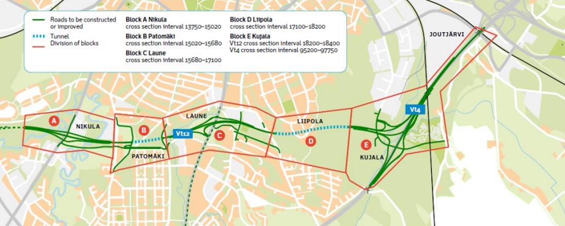
(4) Spatial division of the infrastructure project (source: FTA)
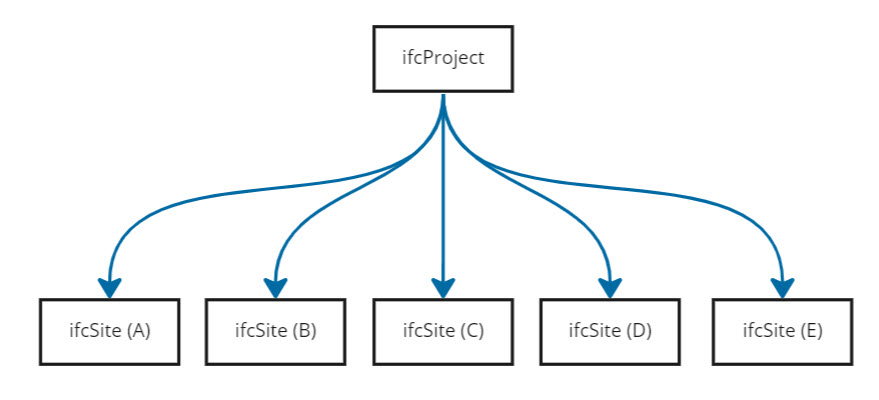
As you can see above, the area where the road project is located is divided into many regions. Each of these areas is a separate study that can have its own status, its own stage of advancement. This is the first level of site subdivision
(5) Decomposition of the project into ifcSite's
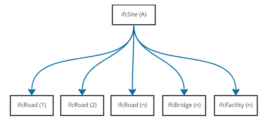
ifcSite Each of ifcSite contains various facilities. These could be roads, bridges, tunnels, water & sewer systems. Thus, the next spatial decomposition of the project is the division into facilities
In the example, ifcSite can be further broken down into the facilities that are in that area.
(6) ifcSite divided into facilities
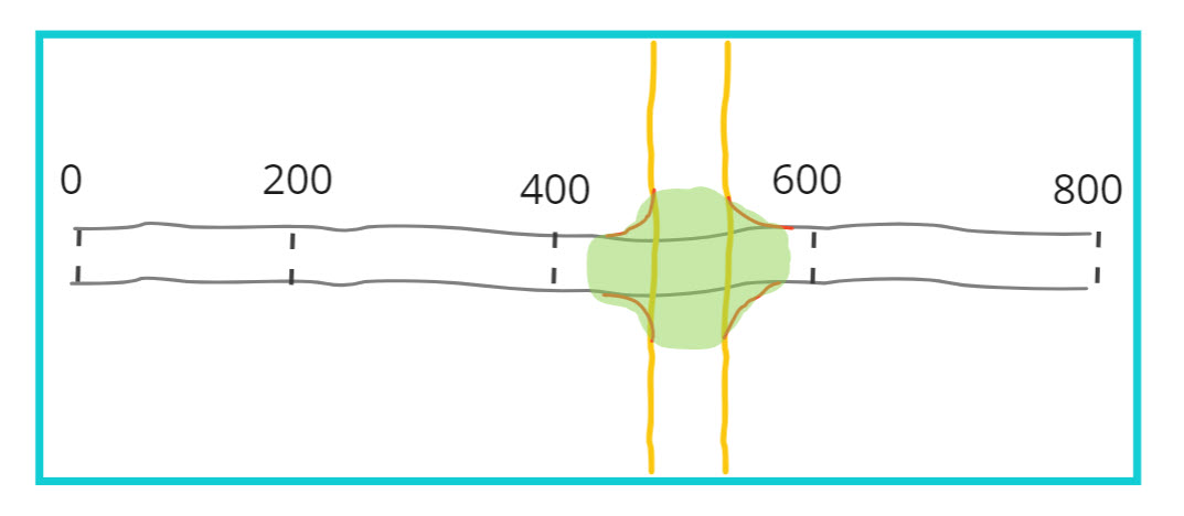
ifcRoad Moving on, let’s analyze how the road can be divided. As I mentioned above, we consider linear structures horizontally. A road can have a long stretch, which means that in many cases it can also be divided into segments according to the main road mileage. Often this mileage may refer to the network (LRS). Thus, the first division of the road is the division into longitudinal sections/segments.
Let’s analyze an example. The Road 1 is 800m long, and in the middle of the length there is an intersection with Road 2.
(7) Road 1 and its segmentation
(8) ifcRoad and its parts in longitudinal dimension
ifcRoadPart Road is divided into three parts located along alignment. Road segment and intersection. An intersection is described spatially only once and refer to all intersecting roads. In this case, the intersection area is part of Road 1. At the same time it is related to road 2 (using ifcRelInterfacesElements)
Example of intersection decomposition
(9) Decomposition of the intersection (source: buildingSMART, Conceptual Model Report, 2020)
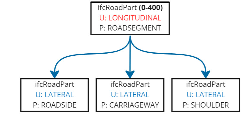
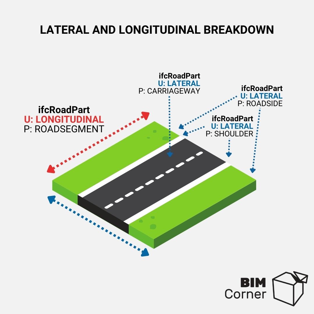
The lowest level of spatial division of the road is the division into parts in the transverse dimension. The road can be divided into areas such as carriageway, traffic lane, shoulder, sidewalk, roadside. These parts are also most often associated with semantic names. Check more here: ifcRoadPartTypeEnum
(10) Lateral division of longitudinal segments of the road
It is worth mentioning that spatial hierarchy can change and evolve during the course of the project. It is also important to understand that each project can have different decomposition. In many cases each road part should be easily presented in 2D and GIS platforms.
(11) Lateral division of longitudinal segments of the road
Where Spatial Breakdown Structure is requested?
Why do we use the spatial division of the project at all? For many reasons. First of all, such a division facilitates asset management. However, a properly created spatial hierarchy in IFC file is used in the following cases:
Visualization Add color, texture to the entire area Turn off objects based on area Visualize status
Coordination Manage disciplines
Collision detection Collision check between objects in a specified area
Reference model Use only part of the design as a reference
4D Construction Sequence Modelling Classify objects and entire areas
Progress monitoring Add status to objects
Use Cases
Below are three breakdowns presented by various software vendors
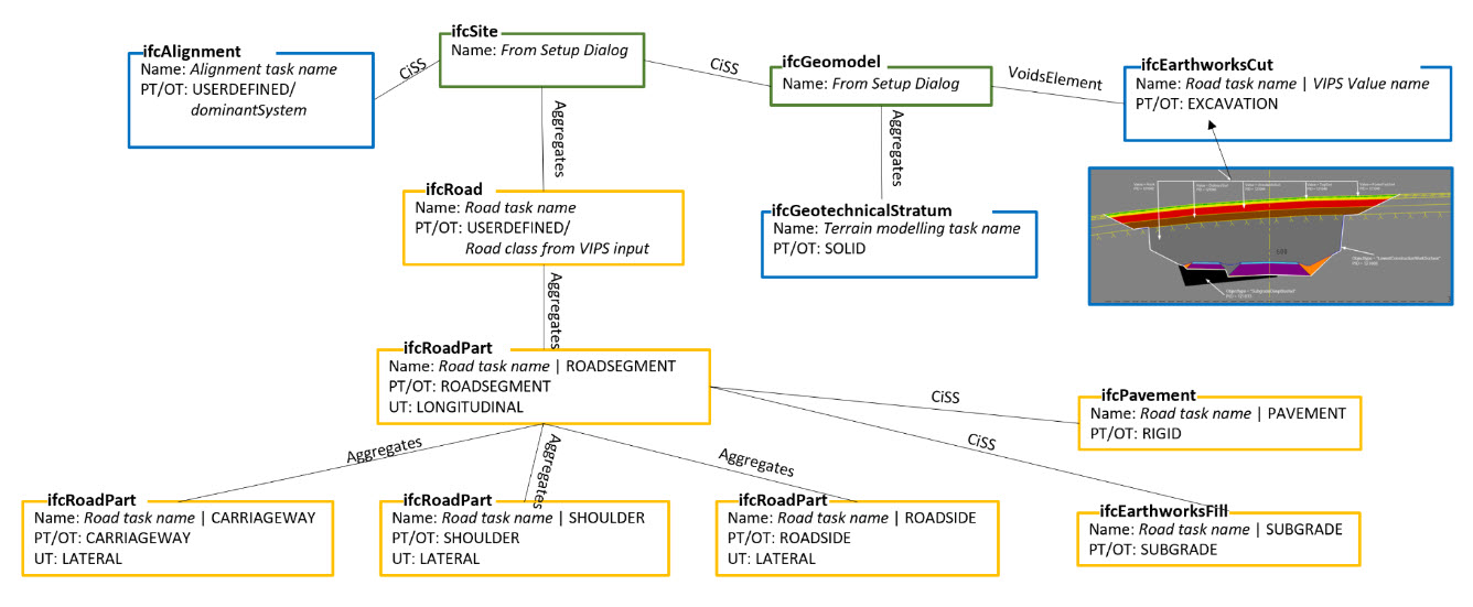
Trimble Novapoint / Trimble Quadri
(12) Spatial decomposition of road suggested by Trimble
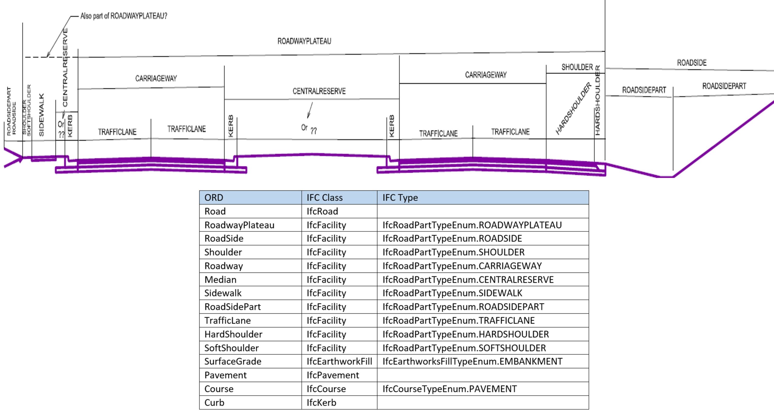
Bentley ORD
(13) Spatial decomposition of road suggested by Bentey ORD
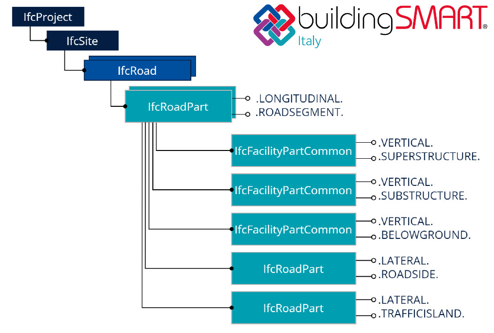
BuidingSMART Italy / SierraSoft
(14) Spatial decomposition of road suggested by buildingSMART Italy
Summary
As you can read, a project can be broken down in many different ways. The division of the project is individual, although it is good to remember about constant assumptions.
Hope you enjoyed the article. Don’t forget to check out the others on IFC 4.3!!
You have successfully joined our subscriber list. Check your inbox. Confirm email in order to get access BIM Case Studies from the biggest Norwegian projects.
Reasons to Subscribe to the BIM Corner List:
BIM CASE STUDIES
After reading this guide, you will learn:
How BIM is used on the biggest projects in Norway
What were the challenges for the design team and how were they solved
What were the challenges on the construction site and what was our approach to them
News From BIM World
Every Thursday you will get a package of news and useful links from the BIM world.
No Hype
Just real content that’s meant to make a difference in your BIM knowledge.
This site uses cookies to offer social functions, analyze traffic and conduct remarketing activities. Details can be found in the privacy policy (info button).