What you should know before starting a project with Tekla Structures
When we talk about BIM, we mean the standards, procedures and processes that are used in the design and construction.
The tools used by designers and managers are also necessary. A list of some of the tools that are used by the BIM Coordinator can be found in the article Ultimate BIM software list for BIM Coordinators
There are software for documentation management, for creating construction and landscape models.
Proper selection of a tool for a given task is a very important element of the design process, which will save time and thus – money. Equally important are the correct settings of the program you are using so that:
each user used the same version (version compatibility)
everyone uses the same layouts, templates, drawing settings.
everyone has access to the user’s components (if such are used in the company)
For a template checklist before starting work in Revit, see one of the previous blog articles.
This article will cover a few steps that are necessary to work effectively using Tekla Structures.
Before we start working with the project.
In every office where Tekla Structures is used, there should be a so-called SuperUser or administrator. Such a person is responsible for managing licenses and updates, but also for preparing settings for the company.
1. Folders Structure
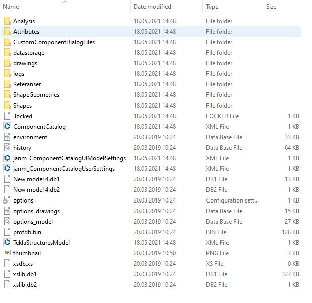
When working with Tekla Structures, remember that a model is not one file in a specific format, such as an AutoCad drawing (.dwg). The model consists of a files and folder structure. The structure of these folders and the order in which they are loaded is important for further work.
Tekla Structures model folder structure
2. Environments
The overriding and most important folder is the settings folder called the environment. It contains settings and country-specific or region-specific information such as:
Profile database – contains information about profiles and their rules, types and materials, as well as analytical and design properties.
Material classes – contains information about material classes and the necessary information about these materials
Default drawing settings – drawing layouts, drawing sizes, etc.
System components – by default, Tekla contains quite a lot of predefined system components, e.g.:
Connections – components connecting two or more elements,
Detail – components that add a detail or reinforcement to the main part. eg: steel beam stiffeners, reinforcement of an RC beam or a spread footing.
3. Firm Folder
This folder is a personalized folder containing program settings and user files for the entire company. These settings are used in all projects carried out by the company.
It can be:
Drawing templates and layouts (e.g. drawing templates with a company logo)
Report templates (Personalized company reports, bill of materials, reinforcement lists etc.)
Special profiles
User components – for the needs of the project, you can create non-standard connections, elements or details. Custom components can be used in the same way as any Tekla Structures system component.
4. Project Folder
In addition to the general settings for a given company, sometimes only project-specific settings are necessary. Often the company is a subcontractor and works on part of the project (e.g. steel structure). The required project settings of the ordering company are placed in the project folder. There can be several or even a dozen such project folders, depending on the specificity of the work and customer requirements.
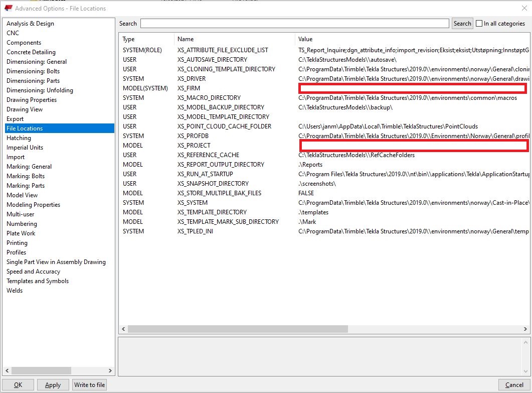
For example, a project may consist of several models made by separate teams working in different locations. Files and settings specific to this project can be saved in the project folder for use by everyone involved. Remember that information about the location of the company folder and project folders should be included in the advanced settings of the program.
Tekla Structures advanced options - a place to specify the path to the firm folder and the project folder
5. Drawing layouts
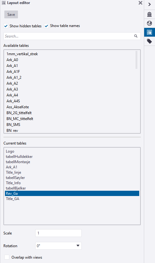
The drawing layout determines which tables are included in the drawing and how they are arranged. Each drawing layout has its own table sets and corresponding drawing sizes.
A set of tables that can be used in the drawing layout
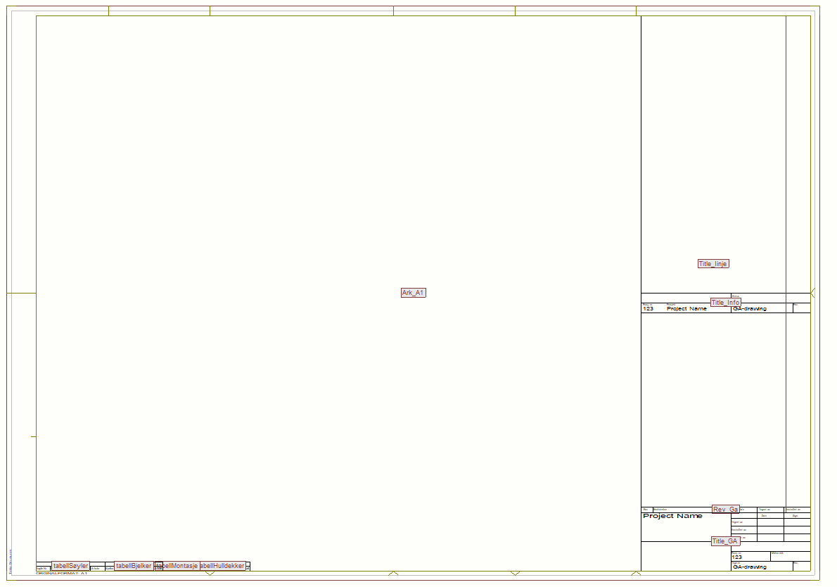
tables located in the drawing layout
The layout of the drawing is related to the dimensions of the drawings. Each drawing type (General Assignment, Assembly, Part) can have its own individual drawing layout with the necessary table sets.
6. Reports
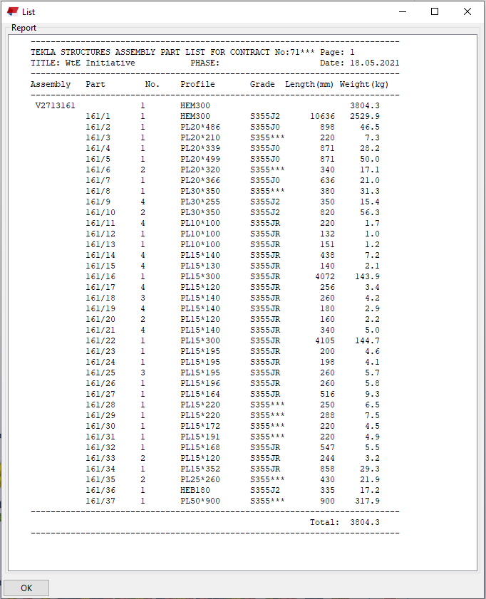
Reports can be created based on information in models. It can be for example lists of drawings, bolts, and parts. Reports are generated directly from the model database, so the information is always accurate. Reports can contain information on selected elements or on the entire model.
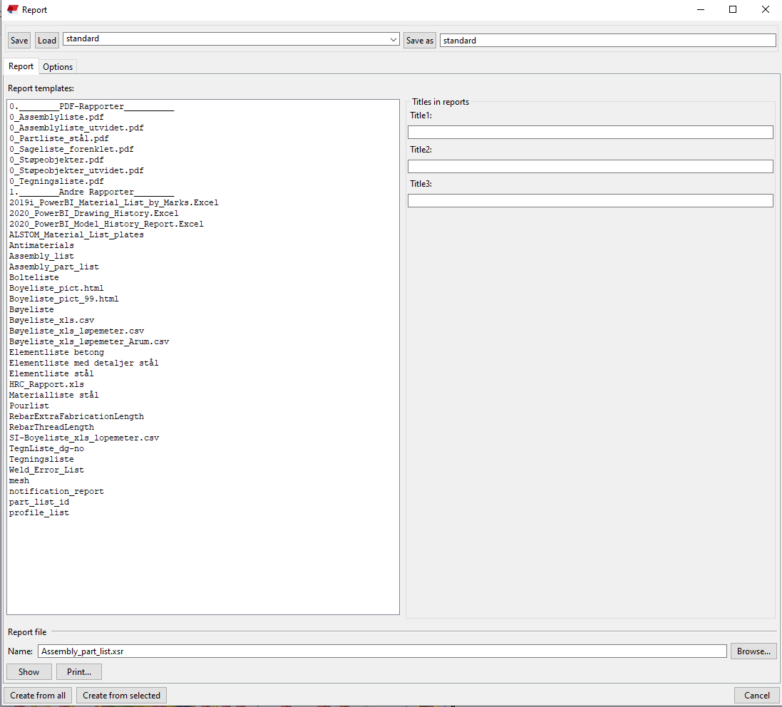
It is possible to create report templates for the company or project (containing company information, company logo or project information). Also, the report format is an issue to be determined when creating the template. It can be an xls format that can be reproduced in Excel or a material list in pdf ready to be sent to the supplier.
List of available report templates
Preview of a sample report generated from the model
7. Project properties
When you start the project, all necessary information is taken from the model. This applies to both reports and data in drawings.
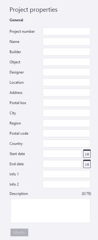
Information such as project number, name, project properties must be completed at the beginning of each project so that reports and drawings automatically include the correct information. All fields are optional.
When you finish editing project properties, the updated project properties appear in the drawings and reports.
The fields in the figure below refer to template attributes that can be used when designing your own reports and templates.
Project information included in drawings and reports
8. Base point
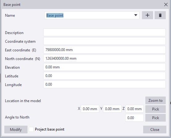
Very often, we only perform part of the structure of a given project and it is necessary to exchange reference models with other industries (MEP, HVAC, Architecture), often also between different companies. Thanks to the base points, we can be sure that we are importing the reference models to the right place, or that our model is exported (e.g. as IFC) with the correct coordinates.
Base point information
It is also makes easier for the BIM Coordinator who gathers disciplinary models into a single coordination model and carries out clash checks.
Export to IFC including base point
You will learn more about IFC export, Property Sets and Creating your own attributes in the following articles.
Summary
It may seem that getting started with Tekla Structures can be quite complicated. However, as with any tool, there is a lot of administrative work involved in the beginning, related to company or project settings and requirements.
Before you start a project, remember a few of the most important things:
Choosing an appropriate work environment related to the project region (e.g. Poland)
Defining the Firm folder settings from which all company-specific settings and files will be derived.
If necessary, check if the project folder is specified
All information, personalized files and settings from the company folder and project folder are automatically loaded into the model.
Specify the information that will be necessary for drawings and reports in the project properties.
Define the base point, i.e. project coordinates, to exchange of reference models and facilitate the work of the BIM coordinator.
Did you like that post ? Share it with others !
We spend a lot of time and effort creating all of our articles and guides. It would be great if you could take a moment to share this post !
You have successfully joined our subscriber list. Check your inbox. Confirm email in order to get access BIM Case Studies from the biggest Norwegian projects.
Reasons to Subscribe to the BIM Corner List:
BIM CASE STUDIES
After reading this guide, you will learn:
How BIM is used on the biggest projects in Norway
What were the challenges for the design team and how were they solved
What were the challenges on the construction site and what was our approach to them
News From BIM World
Every Thursday you will get a package of news and useful links from the BIM world.
No Hype
Just real content that’s meant to make a difference in your BIM knowledge.
This site uses cookies to offer social functions, analyze traffic and conduct remarketing activities. Details can be found in the privacy policy (info button).