IFC 4.3 represents an undeniable breakthrough in the Architecture, Engineering, and Construction (AEC) industry. This new version of the standard brings with it a series of key modifications and enhancements that have a significant impact on infrastructure projects. In this article, we will discuss in detail how these changes in the IFC schema directly translate into adapting this standard for infrastructure projects.
Here are seven key changes that make IFC 4.3 an attractive choice for infrastructure projects, which we will discuss below
1. Disciplines
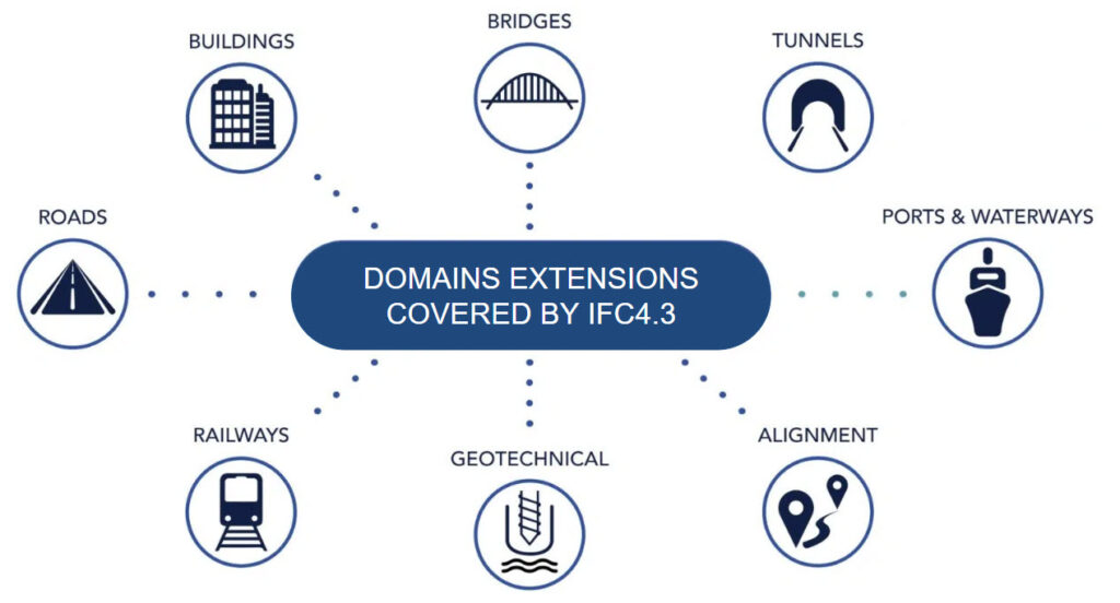
The primary goal of the IFC 4.3 update is to expand the schema to provide a detailed description of infrastructure projects in areas such as railways, roads, ports, and waterways, including common elements for these fields (geotechnics, alignment).
As a result, 62 new entities and 294 new predefined types have been introduced, allowing for an even more precise description of infrastructure elements. This is a significant step forward in accurately representing objects in such projects.
2. Coordinate Reference System
Coordinate Reference Systems (CRS) are crucial for infrastructure projects as they provide a standardized way to locate and position elements within the project area. They ensure that various elements like roads, bridges, installations, and buildings are accurately synchronized with each other and with existing objects in the analyzed area. Determining CRS enables a consistent and standards-compliant approach to data exchange.
Without a consistent CRS, there is a risk of improper location, which can lead to inefficiencies, safety hazards, and potential project delays. This approach has been supported since IFC 4, introducing new objects for object placement, such as IfcCoordinateReferenceSystem, IfcProjectedCRS, and IfcMapConversion.
3. Triangulated Irregular Network
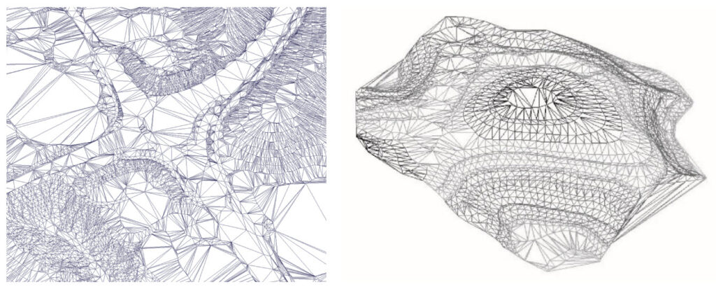
The Triangulated Irregular Network (TIN) allows terrain modeling by representing it using triangles. This enables accurate topographic analyses, including slope, gradient, and other terrain characteristics, which are crucial for infrastructure planning.
It’s worth noting that TIN has been available since IFC 4×1.
4. Alignment
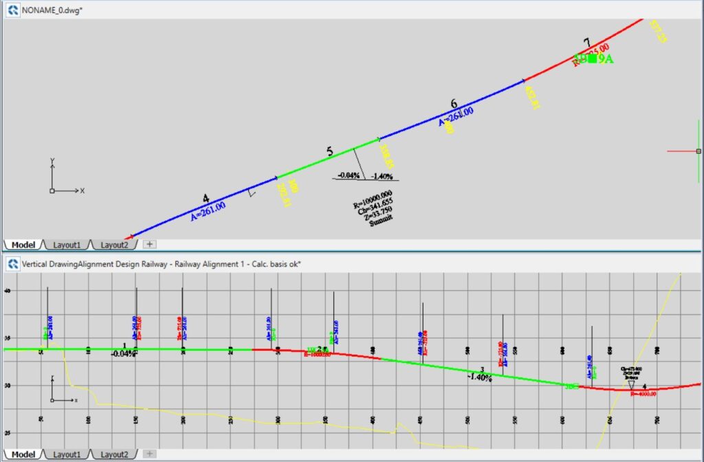
ifcAlignment is an element of the Industry Foundation Classes (IFC) standard that allows for precise descriptions of longitudinal objects in infrastructure projects. It’s a significant step forward as it facilitates the accurate representation of route lines.
4.1. Horizontal and Vertical
In terms of horizontal and vertical geometry, the IFC standard provides specific objects that allow for precise representation. Two key objects are ifcAlignmentHorizontal and ifcAlignmentVertical. The former allows for an accurate description of horizontal geometry, including transition curves, straight segments, and other alignment characteristics. The latter, ifcAlignmentVertical, enables precise modeling of vertical geometry, such as gradients, level differences, and other height-related aspects.
4.2. Cant
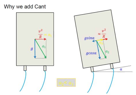
ifcAlignmentCant in the IFC schema allows for a more comprehensive consideration of all relevant aspects of the railway track’s geometry. It enables precise modeling of cant, which is crucial for curved rail alignments.
4.3. Placement & Stationing
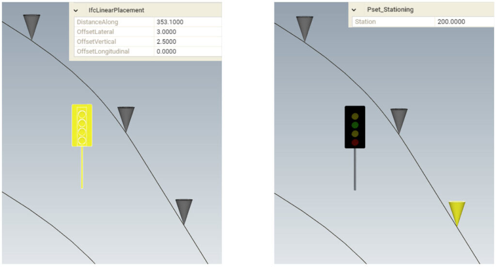
Additionally, the IFC standard provides mechanisms for precise object placement along alignment lines. It allows for distance determination along the alignment, both horizontally and vertically. Moreover, there is functionality for determining the kilometerage along the route.
5. Geometric Representation
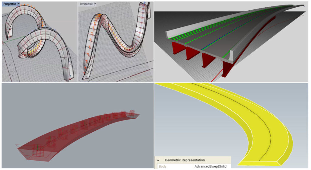
The IfcSectionedSolidHorizontal object, introduced with IFC 4.1, allows for cross-sections along the alignment where the cross-section’s y-vector is maintained in the global z-direction. This innovative approach differs from the conventional IfcSweptAreaSolid, where the cross-section is maintained perpendicular to the direction of movement at any given time. IfcSectionedSolidHorizontal was introduced to accurately model elements of infrastructure objects, such as road layers or bridge decks.
6. Objects
6.1. Physical Elements
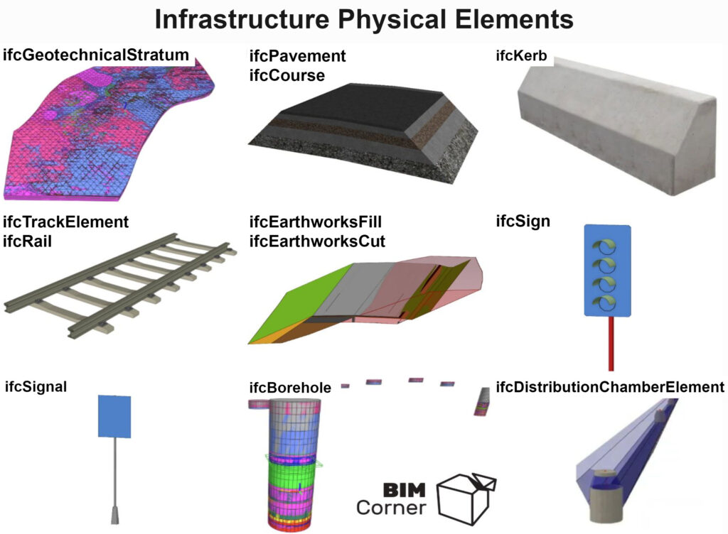
The latest version of the standard introduces many objects that allow for a more detailed description of elements found in infrastructure projects. Now, there is the capability to describe elements such as terrain, road/rail layers, curbs, tracks, foundations, earthworks, signals, signs, geotechnical boreholes, and drainage ditches.
6.2. Annotation
6.3. New Proxy
The ifcBuildingElementProxy object is likely one of the most popular choices when you’re uncertain about which object to use for describing your elements. In the latest version of the IFC standard, objects that might be challenging to assign to other categories will be allocated to the ifcBuiltElement object.
7. Spatial Elements
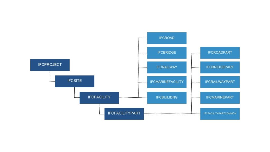
With the latest change in the IFC schema introducing spatial abstractions/objects, we can better organize models. This allows for clearer communication and structuring of the project division. Previously, in the case of infrastructure projects, there was a lack of this possibility. Objects exported to earlier versions of the standard were assigned individually, significantly complicating the interpretation process. Each project had its own guidelines, making it difficult to establish a unified project division.


