

Two renders of the same 87 m concrete bridge. Same geometry to the millimetre, same colours, same camera. One of them will come back from the client with corrections. Nothing on the screen tells you which one.
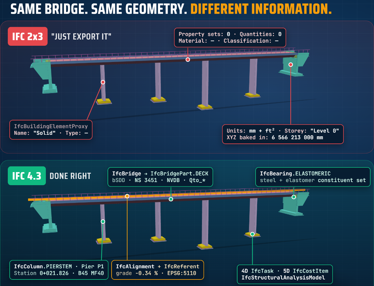
I exported this bridge (BR-01, a real Tekla model) three ways and read the files side by side. This article is the written version of that comparison: the numbers, the real lines from the files, five searches you can run on your own model in a text editor, and two mistakes I found in my own “best” file.
| File | Schema | Proxies | Properties | Size |
|---|---|---|---|---|
| 01 Bridge_BAD_generic | IFC 2×3 | 161 | 0 | 2.5 MB |
| 02 Bridge_GOOD | IFC 2×3 | 0 | yes | 0.8 MB |
| 03 Bridge_BEST | IFC 4.3 | 0 | 1,770 | 0.8 MB |
Read the last column twice. The file that knows nothing is three times larger than the file that knows everything. We will see why.
1 · Five searches in a text editor
An IFC file in STEP format is plain text. You do not need any software to start checking it. Open it in Notepad++, VS Code or any editor and count these five words:
| Search for | What it tells you | 01 | 02 | 03 |
|---|---|---|---|---|
IFCBUILDINGELEMENTPROXY |
objects with no real class | 161 | 0 | 0 |
IFCALIGNMENT |
a real alignment, not a polyline | 0 | 0 | 1 |
IFCPROJECTEDCRS |
the model knows where it is | 0 | 0 | 1 |
IFCQUANTITYVOLUME |
quantities as numbers | 0 | 298 | 580 |
IFCWORKSCHEDULE |
a construction schedule | 0 | 0 | 1 |
✔ Check it on your model today
- Proxies. Any number above zero means objects nobody can filter, quantify or check by type.
- Alignment and CRS. For a road, rail or bridge in IFC 4.3, zero means the model does not know where along the route, or where on Earth, it is.
- Quantities. Zero means every volume and area has to be measured again by the receiver.
2 · Four questions to the same bridge
A client asks four questions without thinking. Each answer lives at a different address in the file.
What is this object?
The same pier P1, in the three files:
01  #92=IfcBuildingElementProxy('1Iw7Gbn7TFke4P2HpYRTgJ',#5,'Solid',$,$,#90,#91,$,$)
02  #201=IfcColumn('0orICgdHPSlR49FPc2z3O2',...,'Pier wall P1',...,'Pier wall',...,'PW-P1')
03  #252=IfcColumn('0orICgdHPSlR49FPc2z3O2',...,'Pier wall P1',...,'PW-P1',.PIERSTEM.)
File 01 says “Solid”. File 02 says column, and “Pier wall” is free text that a machine can only guess at. File 03 says it in the schema: PIERSTEM. Notice the GlobalId too: identical in 02 and 03, random in 01. Random GlobalIds break every issue list and every comparison between two versions of a model.
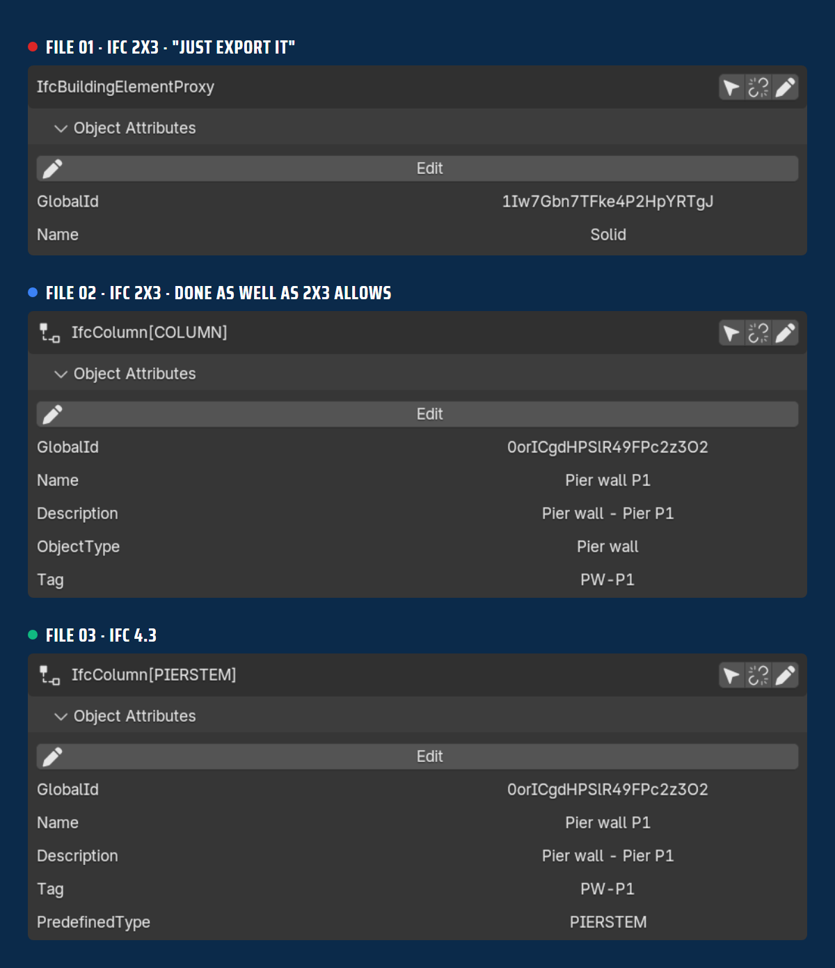
PredefinedType PIERSTEM.The bearings show the limit of IFC 2×3. The best it can do is a generic IfcDiscreteAccessory with a label. IFC 4.3 has IfcBearing with a predefined type (here ELASTOMERIC).
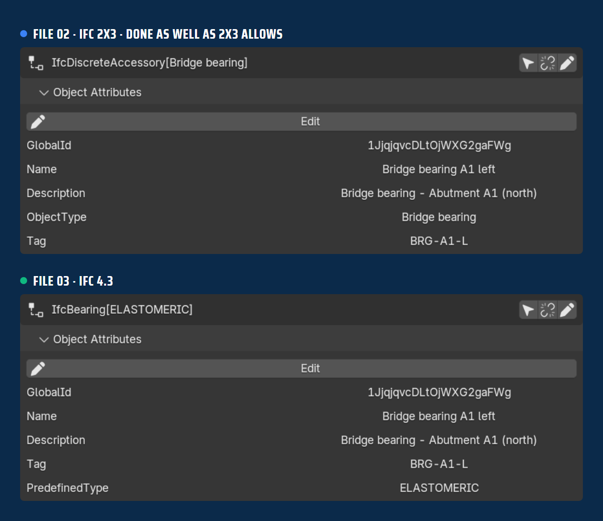
IfcDiscreteAccessory in IFC 2×3, IfcBearing ELASTOMERIC in IFC 4.3.Where does it belong?
Open the tree. In the IFC 2×3 file the bridge is an IfcBuilding and pier P1 is an IfcBuildingStorey. It works, and it reads wrong. In IFC 4.3 it is IfcBridge → IfcBridgePart SUBSTRUCTURE → IfcBridgePart PIER 'P1', and four physical elements (the pier, its footing, blinding and stone bed) are contained in that part.
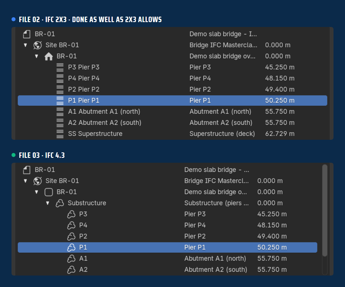
More on this in Your road is living in a building storey.
Where along the bridge?
IFC 2×3 has no alignment. So the station of P1 is a number somebody typed into a property set:
02 #11315=IfcPropertySingleValue('Station',$,IfcLengthMeasure(21.826),$)In IFC 4.3 the station is a position on a real IfcAlignment: a horizontal and a vertical layout with real segments, an IfcReferent carrying Pset_Stationing, and IfcRelPositions tying pier P1 to station 0+021.826.
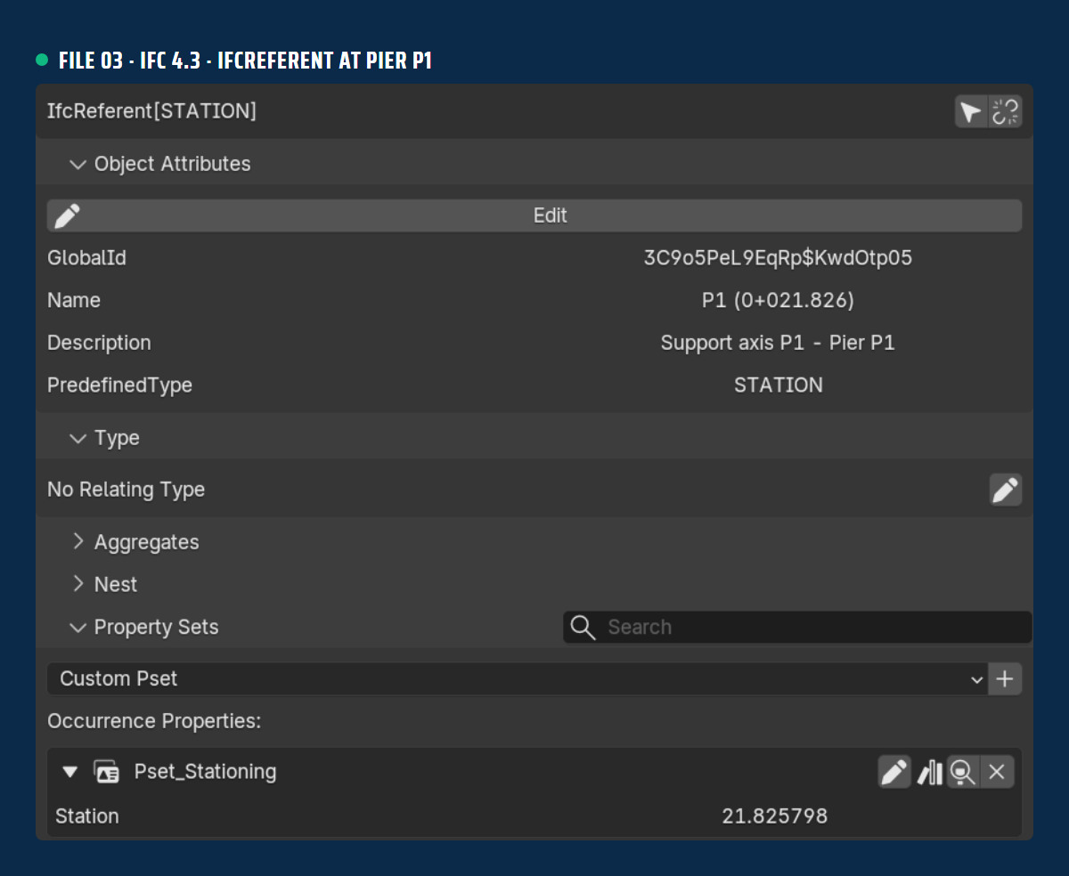
Pset_Stationing. File 03, Bonsai 0.8.5.Where on Earth?
This was the result that surprised everybody. File 01 has no georeferencing. Instead, the national grid coordinates are baked into every vertex, in millimetres:
01 #37=IfcCartesianPoint((145717840.5,6566197332.7,63000.))Many viewers and engines draw in 32-bit floats, roughly seven significant digits. At 6,566,197,333 mm the smallest step they can represent is about half a metre. The geometry jitters, clash tests lie, federation breaks, and the screenshot still looks perfect.
In IFC 4.3 the offset lives once, at file level, and the geometry stays small:
03  #46=IfcMapConversion(#33,#45,145700.,6566100.,0.,1.,0.,1.)
    #45=IfcProjectedCRS('EPSG:5110',...,'NN2000',...)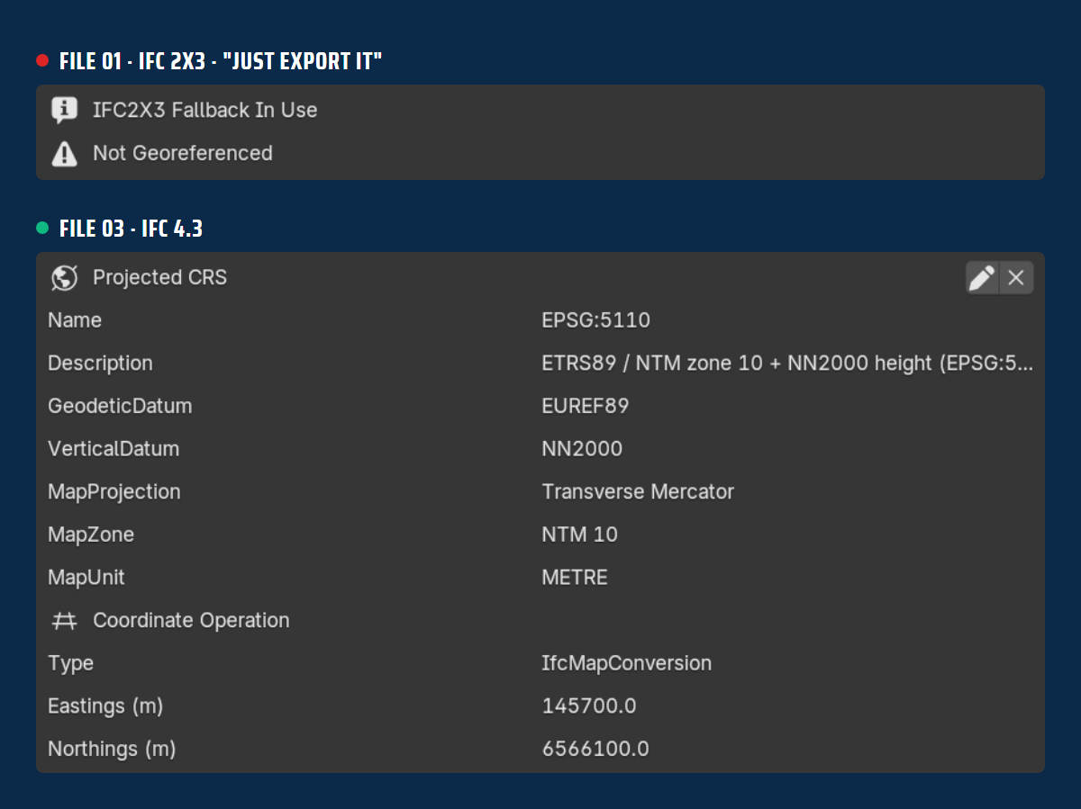
EPSG:5110 and IfcMapConversion.To be fair to IFC 2×3: an almost empty IFC 2×3 file is an export problem, not a schema problem. File 02 carries classes, types, materials, property sets, quantities and classification. What IFC 2×3 cannot store is the bridge, the alignment, the bearing and a real coordinate system.
And the file size? File 03 replaces thousands of triangles with extrusions and defines one railing post once for 98 posts. Geometry entities drop by 95 %. More information, a smaller file.
3 · Even a “best” file hides mistakes
I found two in mine
- The schedule. Only 51 of 151 elements carry a construction task directly. The railing posts were reached only through
IfcRelAggregates. The full story is in the 4D article. - The cost plan counted the concrete twice. The cost item picked up
NetVolumefrom two quantity sets with the same property name. Fixed: 1,414 m³, not 2,829.
Same name, two addresses. That is exactly why you inspect a file before you deliver it, even when you built it yourself.
4 · Five steps before you deliver
- Understand. Write down what the client must find in the file, and where. That list is your future IDS.
- Structure. Decide the facility, the parts, the classes and the predefined types in the authoring tool. The exporter cannot invent them.
- Export. Same geometry, different mapping: schema, classes, properties, units, coordinates, GlobalIds.
- Inspect. Open the file. The five searches above take two minutes.
- Verify. Three gates: the schema, the buildingSMART Validation Service, and your IDS. A valid file is not yet a complete file.
IFC 4.3 will not clean a messy model. It removes the excuse: infrastructure finally has the vocabulary. What you say with it is still your decision.
Want to look at the three files yourself? Open them in the free demo of the Road to BIM IFC Viewer and download them from there. It runs in your browser and nothing is uploaded. The full webinar recording is on YouTube until 16 October.
Enrolment open · closes 16 October
IFC Infrastructure Masterclass, Edition 2
From the structure of the file to a model that passes
This article is one evening. The Masterclass is the whole path, on this bridge and the rest of the model set: road, rail, tunnel and utilities in one coordinate system. Spatial structure, alignment, georeferencing, geometry, data, and in Workshop 6 the full openBIM loop with IDS, BCF and AI.
Six live workshops · Mondays from 26 October 2026 · recordings with lifetime access
From €459. 14-day money-back guarantee on Practical Knowledge and Full Access. Enrolment closes on 16 October.