

BIM technology means processes, software, and the information generating many outcomes. Yet, BIM wouldn’t be so effective if it wasn’t for the standardization of these processes. Hence, standardization is accompanied by standardized terminology.
However, it will not be a compendium of terms and concepts related to BIM simply because there is just a great number of them. In the following article, I will focus on several major and most popular concepts. If you are looking for a database of all BIM terms, please visit:
This article is one of the first to be published on our blog. This time I’ve added links to newer articles in which these terms are fully described.
This will allow you to better understand what these terms are.
1: 2D (CAD)
The way of designing and documentation is done and delivered in two dimensions. Any coordination is based on individual drawings. Characteristic for BIM level 0.
2: 3D (BIM)
Modeling 3D objects in such a way that they contain information in the project. In other words, the model is not only a three-dimensional representation of objects, but also provides all the information necessary to prepare the project documentation.
The model is, therefore, a source of information for generating drawing documentation as well as reports and material combinations, etc. Modeled objects are parametric and any changes in the model affect the generated drawings or reports.
3: 4D (BIM)
3D model with information concerning the time and sequence of installation of specific object elements. The time of construction, fabrication time, assembly time, delivery time for construction, etc. can also be specified. Thanks to the model with the time information, it is possible to create a simulation of the object construction.
4: 5D (BIM)
3D BIM model with information about the time of installation of specific elements and their cost. Based on this information, an analysis of the object construction costs is performed.
5: 6D (BIM)
3D model along with information enabling the analysis of the impact of construction on the environment and people. Such data may be used for the energy analysis of facilities and the determination of carbon footprint.
6: 7D (BIM)
3D model extended with the information necessary for the management and operation of the construction. The model is frequently used as the basis for specialist FM (Facility Management) platforms.
7: IFC - Industry Foundation Class
An open data record format developed by buildingSMART for the transfer of information and coordination between different process participants. The main advantage of such a format is its openness. Thus, it is possible to use it through software from different manufacturers (interoperability).
IFC files contain all relevant object data such as geometry, location in space, individual elements data, element attributes. An increasing number of projects in Norway involves drawingless projects, in which IFC is the primary information carrier.
If you want to learn more about the IFC format, check out the series of articles dedicated to this topic:
1.Everything worth knowing about the IFC format
2.Secrets of the IFC format part 1
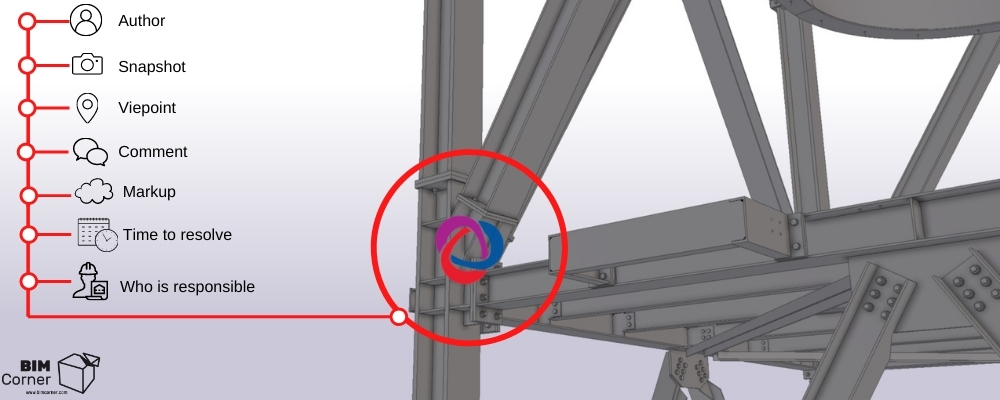
8: BCF - BIM Collaboration Format
A file format developed by Tekla and Solibri for exchanging information and comments in a model between different software. Later adopted as a standard by buildingSMART. The format is implemented as an XML file format (bcfXML), and a RESTful API network service (bcfAPI).
It is designed primarily to define model views and related information on collisions and errors associated with specific objects in the view. It allows you to exchange comments, indicate the place to which the comment applies, its author and the time when the comment was posted. BCF is associated with specific components of the model through its unique global identifiers (GUID).
More about BCF can be found in the article:

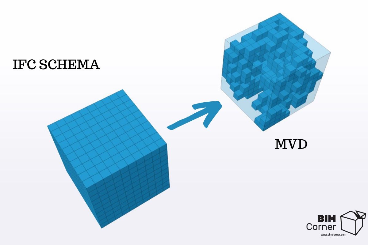
9: MVD - Model View Definition
Is a subset of the general IFC schema to indicate selected data in a model which meets specific criteria or specific data flow. It is therefore easy to extract from the IFC data those necessary at specific stages of the process.
To support BIM interoperability across hundreds of applications, industry domains and regions around the world, the IFC schema is designed to cover many different configurations and levels of detail. MVD is intended to limit the amount of information extracted from an IFC file according to the requirements of the recipient and the specific workflow.
You can read more about MVD on our blog here:
10: CDE - Common Data Environment
Is the central data repository required to perform the BIM Level 2 information sharing function. The CDE collects, manages and distributes relevant validated project documents for multidisciplinary teams at the specified access level.
The CDE platform is generally hosted on an external server which is accessible to all parties involved in the project with the appropriate permissions. The CDE platforms have an automated information flow. Additionally, they use predefined ways of sharing, accepting and commenting documents.
This topic is explained in the article:
11: EIR - Employer’s Information Requirements
Document which explains the requirements of the employer when ordering services. These requirements may concern, among others, levels of modeling detail, requirements concerning training and competence, management systems, data exchange formats, etc.
Learn more about EIR in the article:
12: BEP - BIM Execution Plan
It is a fundamental investment document, prepared by suppliers (typically before signing a contract as Pre-contract BEP) to meet the requirements of the EIR.
It includes roles and responsibilities, rights, standards, methods, procedures, milestones, schedule, information flow strategies, conventions for the nomenclature of drawings, components, models, attributes, as well as IT solutions and the master plan for providing project information adapted to the specific investment program.
Read series of articles dedicated to BEP to understand and learn it:
1. Creating a successful BIM Execution Plan: Part 1
2. Creating successful BIM Execution Plan. Part 2
3. Creating Suksessful BIM Execution Plan. Part 3Plan. Część 3
13: IDM - Information Delivery Manual
Is a document aiming at providing an integrated reference to processes and data required in the project and defining the rules of information exchange in this project. The document clearly defines which information should be provided at particular stages of the process.
The purpose of IDM is to provide the necessary information required to ensure process correctness while reducing the amount of information to avoid unnecessary operations. IDM consists of a Process Map, which describes who is involved in the project and how the activities are divided among the participants.
The document also defines the recommended/expected level of detail (LOD/LOI) of the project applied at each stage. It is only used at BIM Level 2.
14: Process Map
It is a component of the Information Delivery Manual. It explains how the activities are divided among the participants of the process, namely who takes part in the project. The Process Map also defines the elements such as the level of LOD/LOI detail of the project at particular stages.
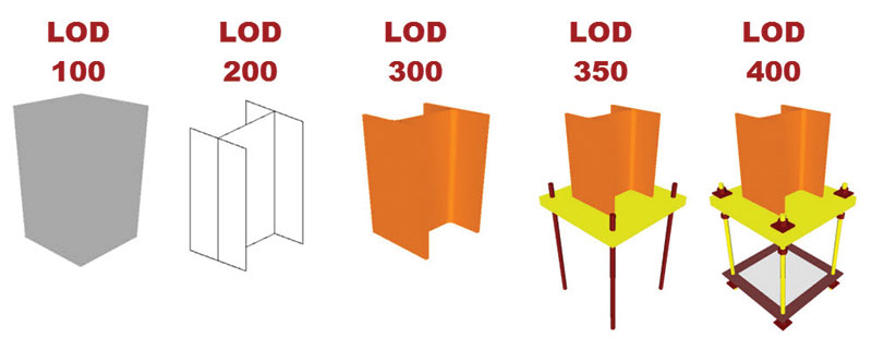
15: LOD - LOD 100, LOD 200, LOD 300, LOD 400, LOD 500 – level of development
Prepared by the American Institute of Architects (AIA) classification of model detail. The level of detail increases with its number. The LOD is employed to determine the required level of detail at each stage of the project.

Source: https://bimforum.org/lod/
16: LOD - LOD1, LOD2, LOD3, LOD4, LOD5, LOD6, LOD7 - Level of Detail
Applied in Great Britain, divided into two types of detail:
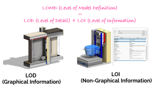
- Level Of Detail – LOD – Refers to the graphic content of the model. It is exactly what you see, the shapes that create the visual model. The level of detail (LOD) is used to define the required graphic content of the model at a particular stage of the project. As the project progresses, the components in the model will be delivered in more detail. For instance, in the case of interior doors, the model may start with a door represented by a simple cuboid, and then additional details will be added as the project progresses.
Sample LOD requirements according to NBS BIM toolkit for doors: https://toolkit.thenbs.com/definitions/ss_25_30_20_30/#lod
- Level Of Information – LOI – The information level determines the non-graphical content of the model at particular stages of the project. As the project progresses, non-graphic details will increase. For doors at the start of a project, the cuboid representing the door will contain limited non-geographical data such as door classification. As the project develops, performance data such as fire resistance, and subsequently manufacturer data, datasheet, etc., will be provided.
Sample LOI requirements according to NBS BIM Toolkit on the example of a door: https://toolkit.thenbs.com/definitions/ss_25_30_20_30/#loi
In fact, both are closely linked, since it is normal for graphical and non-graphical content to develop next to each other. The levels of model detail and model information are generally defined for the key stages of the project where the “data drops” occur (information exchange), enabling the employer to check that the information on the project complies with their requirements and enabling them to decide whether to proceed to the next stage. It is analogous to the stage report of a conventional project.
The combination of LOD and LOI is known as LOMD – Level of Model Definition – meant to define the details required in a model at different stages of the project, both graphical and non-graphical.
Source: http://bimtoolbox.org
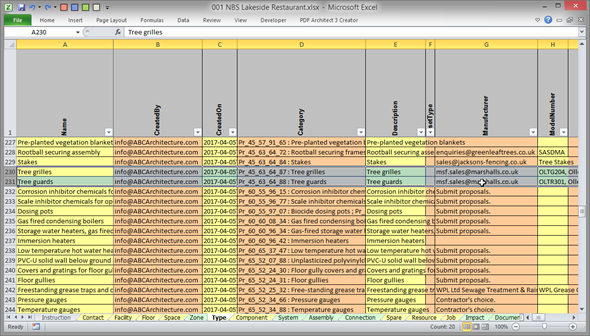
17: COBie - Construction Operation Building information exchange.
A standard of documentation containing data to manage an object in the form of a spreadsheet. It is filled in depending on the project stage. The data in the worksheet includes information on the equipment of the facility along with information regarding each piece of equipment (technical and operational parameters, origin, price, warranty period, date of installation, spare parts lists, inspection dates, etc.).
COBie characteristics:
- Interoperability at the user level – the data recorded in the standard are accessible and understandable to practically any supplier and other participants of the investment process. The data recorded in accordance with the COBie can be easily imported into FM class systems.
- Interoperability at the designer level – majority of the programs used to create 3D models include the option of automatic generation of the COBie file.
- Openness – COBie is compatible with the open IFC format (one of MVC views).
- Multidisciplinarity – the data cover all industries within the object.
- The possibility of applying various classification standards (Omniclass may be required in the USA, Uniclass in the UK and e.g. in Norway the investor may expect the application of the NS-3451 standard).
COBie sample sheet:
Source: https://www.thenbs.com
18: BIM Level 0
System for preparing project documentation in 2D CAD formats. Documentation is mainly distributed on paper or via e-mail.
19: BIM Level 1
System of preparing design documentation, which is a combination of conceptual 3D elements (mainly for visualization purposes) and 2D documentation. Documentation is distributed via CDE (Common Data Environment) platforms.
20: BIM Level 2
BIM maturity level, where the parties cooperating in the project do not co-create one model, but several industry models, which are available among the parties. Exchange of information through a common open file format (IFC, COBie) is essential. Hence the requirement that any software used by the parties involved in the project should be exportable to these files.
The integrated 3D model is, therefore, the primary source of building information, as it contains both geometric and non-geometric data. Level 2 BIM defines levels of model detail and information for individual stages and project participants. The information exchange happens through the CDE (Common Data Environment) system.
21: BIM Level 3
BIM maturity level, which so far is only a concept (i.e. the Holy Grail of BIM). It represents the full cooperation of all disciplines involved in the project in one, common, central model. All project participants have access to the model and the possibility to modify it.

22: VDC - Virtual Design and Construction
VDC is a combination of new technologies (BIM) with an adequate work and management scheme (PPM), supporting people working together on the project, in an integrated and simultaneous way (ICE). The scheme is focused on achieving the project’s objectives, which should help the client to achieve their goals while collecting data and tracking workflow progress.
This topic is explained in more detail in the article:
What is Virtual Design and Construction? VDC definition
Check also the section “Everything about VDC” to learn more about the Virtual Design and Construction.


Nice list – but I think you missed out on one: Reality Capture! RC is all about capturing data on the as-built environment, ideal for tracking construction progress as the project unfurls.