
- IFC 4.3 in road projects – case study
- Relations I used to create IFC 4.3 for infrastructure
- Spatial Breakdown Structure in IFC 4.3
- IFC 4.3 on construction site
- Webinar about IFC 4.3
- Ticket to openBIM
- Export to IFC 4.3
- The Key Changes in IFC Schema Shaping OpenBIM for Infrastructure
- Webinar about IFC 4.3 export from Quadri
In the IFC 2×3 scheme, the pavement layers in the road model are described with ifcSlab and ifcBeam. There is also a lack of spatial division of the project, which is characteristic of the industries involved in infrastructure projects. We can only meet a vertical division of a construction project, the individual levels of which are spatial objects such as ifcBuilding, ifcBuildngStorey.
Of course, you can argue that in projects based on the IFC 2×3 scheme, what really matters is the information on the BIM objects, “at the bottom”. This is due to the fact that there are currently programs that present BIM data in any way we want and allow us to map and catch the information very well. However, such a procedure requires additional work and is not necessarily available to all parties in the project in a uniform and accessible way.
In this context, we can speak of a competitive advantage. Companies that can operate with a large amount of complex data are pioneering the open BIM environment.
An example of such a company is Norconsult. I have already written on bimcorner.com about my work as a BIM Coordinator and about using IFC in this article. In it, I quote the method of describing an infrastructure project using IFC 2×3
Moving on to the essence of the article.
Still, an undeniably well-ordered project according to the appropriate WBS (Work Breakdown Structure) gives more value than a project with an unclear breakdown structure. Our goal should be to create a design that everyone understands, can relate to, and uses the data in an authorized manner. It is therefore crucial to create common standards for the industry that will help streamline processes throughout the project life cycle (supply chain).
Having a common standard, we will be able to adjust systems, set requirements for projects, perform validation, and use digital models in many places.
This is a milestone towards automation.
When we start the project, we should already think about how our data will be used throughout the life cycle of the building.
I would like to invite you to read the article about the IFC 4.3 scheme in a road project.
Introduction to IFC 4.3
IFC Scheme 4.3 is the first to introduce a wide range of definitions to present a construction project in a structured way for the infrastructure industry.
In the context of IFC, three main thematic groups should be distinguished:
- OBJECTS (physical tangible objects, physically existing objects, actors, processes, costs)
- PROPERTIES (characteristic information that can be associated with the object)
- RELATIONSHIPS (dependencies between objects)
In this article, I will introduce the first topic (objects). The next two (properties, relationships) will be discussed in a separate post. I want to describe the objects used to describe the road project and the BIM model. For this reason, I will deliberately omit the subject of actors, processes, costs and resources. (This is definitely a topic to develop in the context of the general IFC schema.)
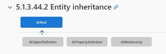
A - OBJECT DEFINITION
The above bricks are abstracts. An abstract can be compared to a conventional set of objects categorizing them at a different level of detail.
I recommend that you familiarize yourself with the entire structure of IFC 4.3 at this link
ifcProduct is an abstract representing any object that corresponds to a geometric or spatial context. The product, if it has geometry, is at a specific location in space. It can be placed relative to other objects, but ultimately relative to a fixed coordinate system.
In addition to physical products ( IfcElement) and spatial elements ( IfcSpatialElement) IfcProduct also includes non-physical elements such as annotation, Cartesian mesh, alignment, etc.
In the context of ROAD MODEL, I will describe the following abstracts:
- ifcSpatialElement – spatial division of a road project
- ifcElement – physical components
- ifcLinearElement & ifcPositioningElement – line segments forming an alignment and its placement
- ifcAnnotation , e.g. stakeout lines
ifcSpatialElement - Spatial division of a road project
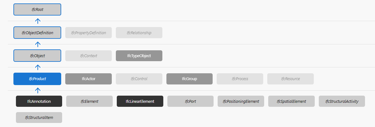
A road, from a technical point of view, is a linear object that is part of a larger road network, eg national roads, provincial roads, etc. The road structure has many accompanying features located along the alignment, i.e. tunnels, road junctions, bridges. The road construction project can be divided into several areas / sites. They usually refer to the main mileage.
In the example above, the project is divided into 5 sites (A, B, C, D, E). Each of these areas is a separate study with its own status, its own stage of advancement. With more complex studies, it is often the case that a different project team is responsible for each study. The division of the project into areas allows the Employer and other actors to better coordinate the design and construction process.
ifcSite is part of ifcSpatialStructureElement, which is part of the ifcSpatialElement
Each of these areas involves the design and construction of several other objects. These are, for example, tunnels, bridges, railways, roads, buildings, technical devices. These structures can be generally called ifcFacility, and the individual types of structures, respectively:
- ifcBridge
- ifcRailway
- ifcRoad
- ifcBuilding
- ifcMarineFacility
- ifcTunnel (soon)

As in the case of ifcSite each of these types is a subcategory of ifcSpatialStructureElement which means that we can use these objects for spatial division of our areas into smaller discipline collections.
The next level of division of a facility object is division into parts. Each part is related to the discipline it represents. In this case we are dealing with the following division into parts:
- ifcBridgePart
- ifcFacilityPartCommon
- ifcMarinePart
- ifcRailwayPart
- ifcRoadPart
PredefinedType, ObjectType, UsageType
PredefinedType
Any object that is a subset of ifcObject can be further characterized using PredefinedType. PredefinedType contains terms characterizing a given object, the so-called enumerations. For example , ifcRail can be used to specify many elements, however, the enumeration, i.e. the value for the PredefinedType for more precise identification of the object.
Enumeration for ifcRail
TYPE IfcRailTypeEnum = ENUMERATION OF
(BLADE
, CHECKRAIL
, GUARDRAIL
, RACKRAIL
, RAIL
, STOCKRAIL
, USERDEFINED
, NOTDEFINED);
END_TYPE;
The exact indication of the object is important as some property sets (Psets) may be specific to one of the object types.
ObjectType
If there is no enumeration for an object, we can define its own type. The ObjectType parameter is used for this purpose. It can be used when the value for PredefinedType is set to USERDEFINED. So with ObjectType we can assign our own value. This can be a value to identify an object according to a taxonomy representing local standards.
For example, ifcRoad has no value for the PredefinedType parameter. In the system, we set the value as USERDEFINED, with the ObjectType parameter we can specify what road it is. It can be your own text, e.g. a motorway, local road, municipal road.
UsageType
In the context of ifcFacilityPart elements, let’s also introduce the UsageType parameter, which in this case is additionally used to characterize the object. For example, a road can be described in various dimensions. We can talk about a longitudinal or transverse division of the road. In the case of longitudinal road division, we mean the division of the road into segments / sections. The lateral division shows the division into characteristic parts such as the road, paved shoulder, ditch.
TYPE IfcFacilityUsageEnum = ENUMERATION OF
(LATERAL
,LONGITUDINAL
,REGION
,VERTICAL
,USERDEFINED
,NOTDEFINED);
END_TYPE;
For example, ifcRoadPart has the following types (PredefinedType):
TYPE IfcRoadPartTypeEnum = ENUMERATION OF
(BICYCLECROSSING
,BUS_STOP
,CARRIAGEWAY
,CENTRALISLAND
,CENTRALRESERVE
,HARDSHOULDER
,INTERSECTION
,LAYBY
,PARKINGBAY
,PASSINGBAY
,PEDESTRIAN_CROSSING
,RAILWAYCROSSING
,REFUGEISLAND
,ROADSEGMENT
,ROADSIDE
,ROADSIDEPART
,ROADWAYPLATEAU
,ROUNDABOUT
,SHOULDER
,SIDEWALK
,SOFTSHOULDER
,TOLLPLAZA
,TRAFFICISLAND
,TRAFFICLANE
,USERDEFINED
,NOTDEFINED);
END_TYPE;


The above figure shows the division of the road into a longitudinal segment (LONGITUDINAL). The longitudinal segment can be further divided laterally (LATERAL). The transverse division allows you to arrange the objects spatially. The road has characteristic elements such as the road, shoulder, sidewalk, ditch. For example, an road barrier should be expected under the ifcRoadPart / ROADSIDE abstract.
Vertical division (VERTICAL) is less frequently used in linear construction. It appears more often in the context of vertical buildings.
Summarizing this paragraph, road construction can be spatially divided into areas (ifcSite), and these in turn into industries (ifcRoad). The road industry can be divided into longitudinal segments (ifcRoadPart) and lateral parts (ifcRoadPart).
Physical components

Each physical object is related to the spatial structure of the project. For example, ifcRoad, divides the model into longitudinal segments ifcRoadPart, and ifcRoadPart in its set contains physical elements that make up road structures.
The physical objects used to describe the road model can be e.g. pavement layers (ifcCourse), earthworks objects (ifcEarthworksFill), reinforced subgrade objects (ifcReplacementSoil), curb ifcKerb, open ditch (ifcPipeSegment). Some of the objects can be combined into one. For example, ifcCourse is part of ifcPavement
Also in the case of physical elements, each of the objects has a PredefinedType parameter that describes a particular type.
ifcCourse
TYPE IfcCourseTypeEnum = ENUMERATION OF
(ARMOUR
,BALLASTBED
,CORE
,FILTER
,PAVEMENT
,PROTECTION
,USERDEFINED
,NOTDEFINED);
END_TYPE;
ifcEartwhorksFill
TYPE IfcEarthworksFillTypeEnum = ENUMERATION OF
(BACKFILL
,COUNTERWEIGHT
,EMBANKMENT
,SLOPEFILL
,SUBGRADE
,SUBGRADEBED
,TRANSITIONSECTION
,USERDEFINED
,NOTDEFINED);
END_TYPE;

ifcPositioningElement & ifcLinearElement
An ifcLinearPositioningElement is an abstract entity describing positioning according to a curve. The ifcAlignment is a subtype of ifcLinearPositioningElement and is used to describe an alignment in a road project. It is also used to define the referencing and positioning of elements along linear structures such as roads, railways, bridges and others. The placement of features along the alignment is determined by the Linear Referencing System methodology.
Following the principles of IFC modeling, alignment elements are organized into two large parts. Both parts work together, but can also be used independently of each other
- Business aspects of the alignment – Here the emphasis is on the structure of the schema as close as possible to the business terminology. It is possible to have a very detailed segment structure with many domain-specific properties attached. Examples of domain-specific properties are design speed or cant
- Representation with IFC geometry resources – The emphasis here is on using as many fixed IFC geometry elements as possible. A mapping between the business aspects and the geometry of the IFC is proposed.
In IFC, a single alignment must have horizontal (X / Y) geometry in the adopted datum. In addition, it may have:
- Vertical geometry, along the horizontal, in space Z
- Additional alignment (e.g., offsett)
- 3D geometry (calculated from horizontal and vertical information, or from geospatial data)
ifcAlignment will contribute to other objects such as:
- ifcAlignmentSegment,
- ifcAlignmentCant,
- ifcAlignmentHorizontal,
- ifcAlignmentVertical.
The ifcAlignment topic is a very complex topic. Over the years, a very large number of materials have been created. In order to increase knowledge in this area, I recommend that you read the buildingSMART technical documentation at this link
ifcAnnotation
Annotations include extra points, curves, text, dimensioning, hatching, and other forms of graphical annotations. It also contains virtual or symbolic representations of additional model elements that do not represent products or spatial structures, such as event elements, measurement points, contour lines, etc.
For example, the edges of pavement layers or individual components, are important information for surveyors. By using ifcAnnotation, we can save this information that can be used on the construction site as stakeoutdata.


This is a pleasure to see. someone who has actually looked at the schema we have worked with for so loong. Thank you Marcin for this. I will definately share it
Thank you