While browsing the blog entries, you have probably noticed how much space we devote to the IFC. You will find quite a bit of general information about the schema (IFC secrets series) as well as a more detailed approach to the topic regarding the export rules depending on the purpose of the model (IFC export rules).
I will not repeat why the topic of IFC export, reference models, collaboration and coordination with the use of IFC is so important in the AEC industry. You can read about it in Konrad’s articles, which I strongly encourage you to do.
In the topic of IFC on our blog, we try to move from general information on IFC to more specific issues in the series on export rules, to detailed advice on exporting from specific structural modeling programs.
This post is about IFC export from Tekla Structures. In the following posts, we will present how to export to obtain a valuable IFC model in other popular programs (Revit, ArchiCAD).
BEFORE EXPORT
Export to IFC in most programs is very intuitive and probably everyone who works in any structure modeling program can easily perform such an operation. Just find the export tab, choose the appropriate format and … ready.
But as Konrad already mentioned in his entries, it is worth considering a few issues before we start exporting the model. For example, what is the purpose of an imported model. Will it be a reference model (so geometry alone is enough), a model for interdisciplinary coordination or for cost estimation?
Before exporting, it is worth checking the classification of objects in the model. Tekla Structures automatically assigns an object classification according to the table below:
| Obiekt programu Tekla Structures | Obiekt IFC |
|---|---|
| Beam | IfcBeam (IfcMember) |
| Column | IfcColumn, (IfcPile), (IfcMember) |
| Plybeam | IfcBeam, (IfcMember) |
| Curved beam | IfcBeam, (IfcMember) |
| Pad footing, Strip footing | IfcFooting |
| Slab | IfcSlab |
| Panel | IfcWall lub IfcWallStandardCase |
| Contour plate | IfcPlate lub IfcDiscreteAccessory |
| Bolts, nuts and washers | IfcMechanicalFastener |
| Bolt holes | IfcOpeningElement |
| Vertical braces | IfcMember |
| Railings | IfcBeam, IfcColumn, (IfcRailing) |
| Assemblies, cast units | IfcElementAssembly, (IfcRailing), (IfcRamp), (IfcRoof), (IfcStair), (IfcWall) |
| Assembly sub-parts | IfcElementAssembly |
| Tekla Structures project | IfcProject |
| Item | IfcDiscreteAccessory |
| Bar, wire, strand, mesh, tendon, and other component embedded in concrete | (IfcReinforcingElement) |
| Reinforcement | IfcReinforcingBar |
| Pour object, pour break | IfcBuildingElementProxy |
| Surface treatment | IfcCovering |
| Weld | IfcFastener |
This means that the classification is assigned automatically (classes in the table without parentheses).
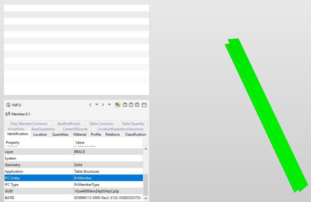
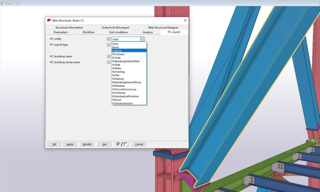
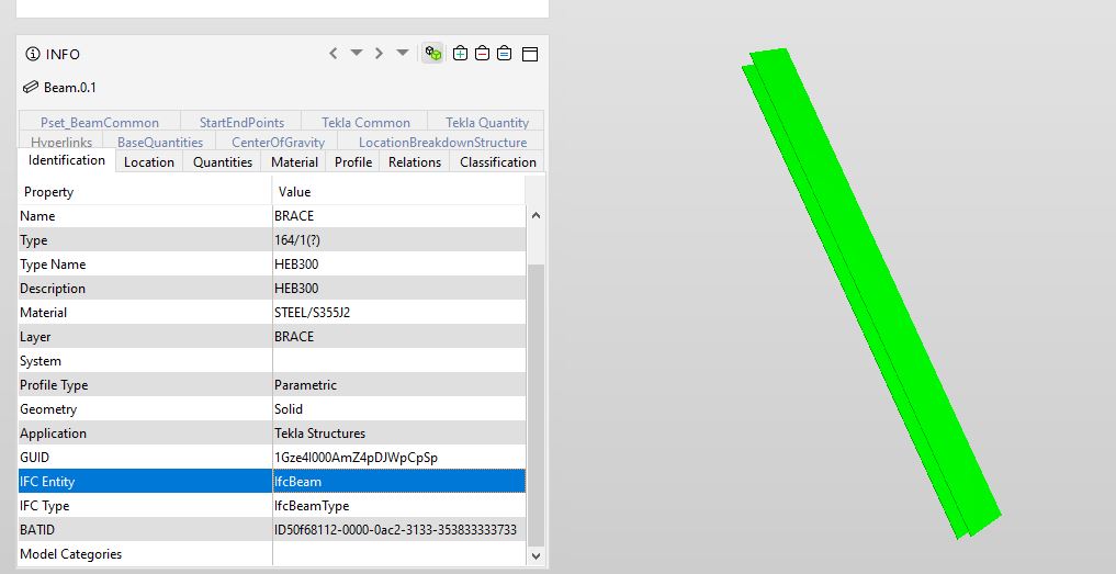
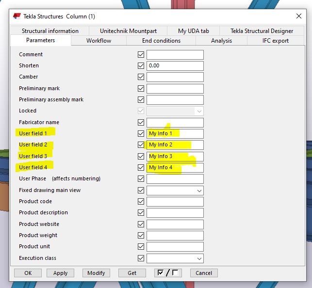
However, it is possible to change the classification of an object from the automatically assigned value (classes in parentheses). How to do it is shown in the pictures below.
In the IFC export tab of the object in Tekla structures, it is possible to select the classification for the object. In this case, e.g. on IfcBeam.
Everything, of course, depends on the requirements contained in the BEP or in the company’s internal procedures.
EXPORT
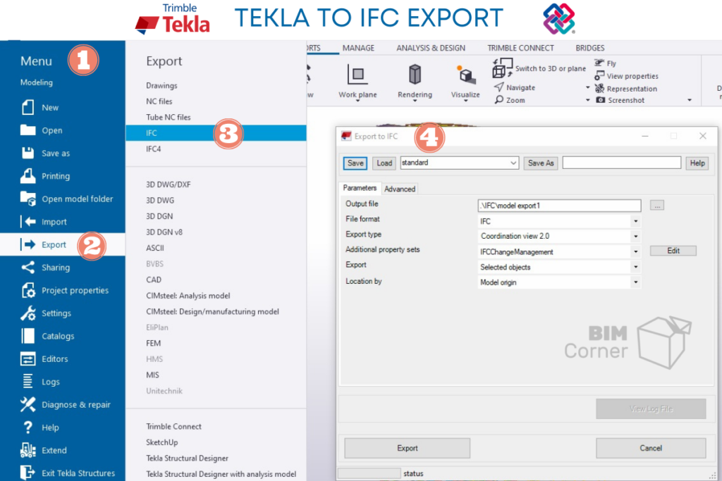
You can actually export to IFC in just a few steps.
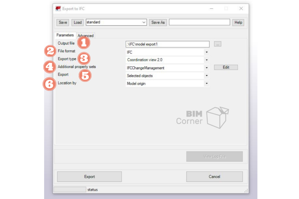
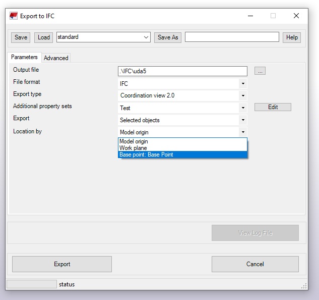
However, before you export the model (or part of it) to IFC, pay attention to the options available in the export menu. In the points below I will explain the individual parameters of the export:
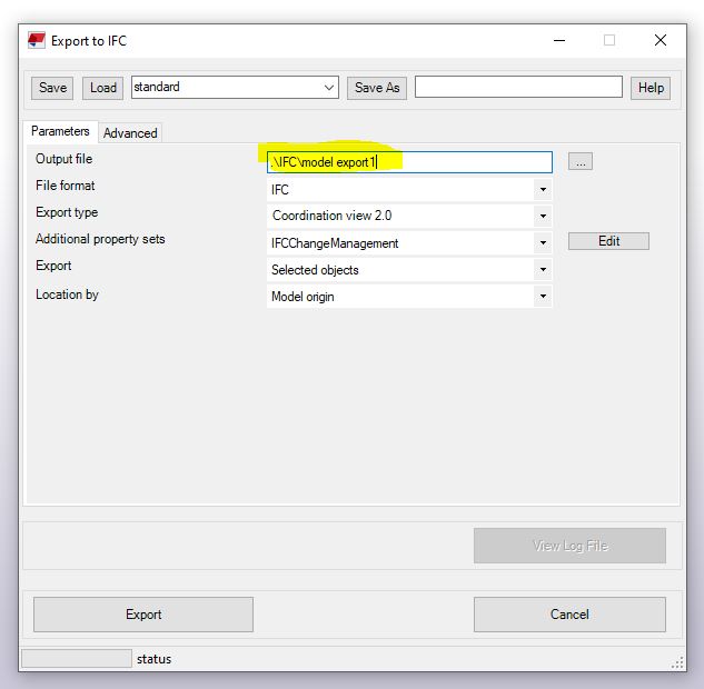
1. Output file
The first point of export is where the exported file is (by default, a directory called IFC is created in the model folder). An important point in this point is to give an appropriate name, usually in line with BEP guidelines. Giving an appropriate name is important from the point of view of coordination, as it usually includes a part that defines the industry (e.g. Construction, MEP, Architectura, etc.)
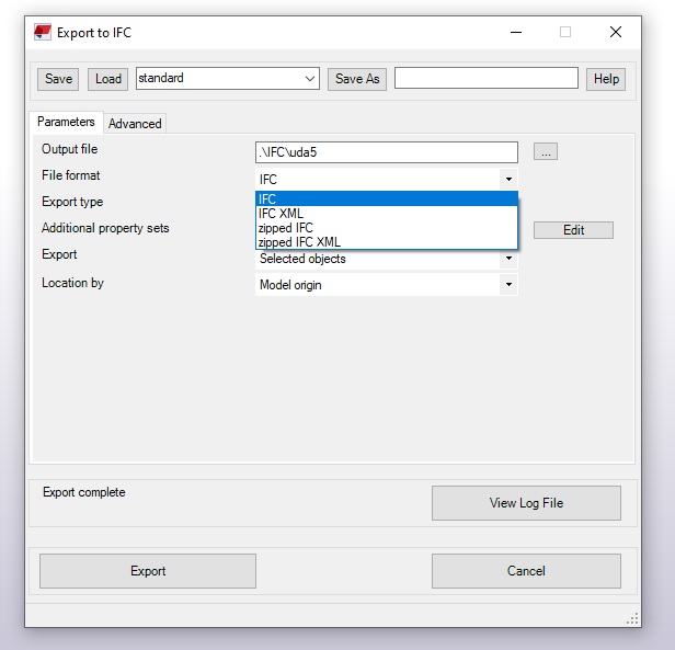
2.File format
Decide which IFC format to export. In the vast majority of cases, you export the standard IFC model. However, it’s worth knowing that there are also other variants that I mentioned in one of the previous articles.
Below is a reminder of the differences between each type of IFC model export:

This is the default exchange format represented by a plain ASCII text file (only text, without formatting). The scheme defines how the text of the file is transformed into objects connected by mutual relations.

IFC data file is using XML document structure instead of ASCII like it was in the standard .ifc file
The .ifcXML file is usually 300-400% larger than the .ifc file.

It is a standardized .ifc or .ifcXML compression format (using appropriate compression algorithms). This is possible because both .ifc and .ifcXML are saved as text files.
.IfcZIP files usually compress the .ifc file by 60-80% and the .ifcXML file by 90-95%.
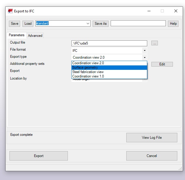
3. Export type
In the article on export rules, you learned how important the destination of the exported model is when exporting to IFC. Different sets of information and parameters are needed for coordination, others for costing or fabrication, and a minimum number of them is needed for reference.
- Coordination View 2.0 – this is a recommended, certified type of export, especially when the model will be edited and modified at a later stage of the work (e.g. by converting the IFC model to native objects of another program)
- Surface Geometry – If the model is used for display purposes only or as a reference model.
- Steel Fabrication View – Recommended for exporting details of steel objects for production.
- Coordination View 1.0 – Suitable when you need to export holes as separate bodies.
It is therefore important to choose the right type of export. Tekla has 4 predefined types of export, depending on the purpose of the exported model. These are:
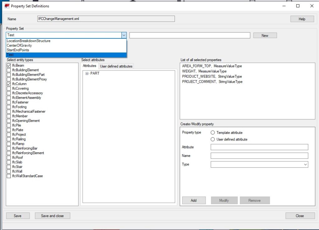
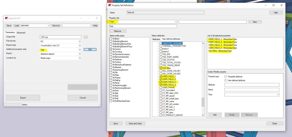
4. Additional property sets
Property Sets are a list of attributes that can be assigned to an IFC model object.
The properties included in this set can be of two types:
- predefined;
- additional / customized (i.e. user defined).
Predefined properties in a property set are defined as part of the standard; they are automatically generated by the proprietary software we used to model the design and are listed in the specification of each element of the 3D model.
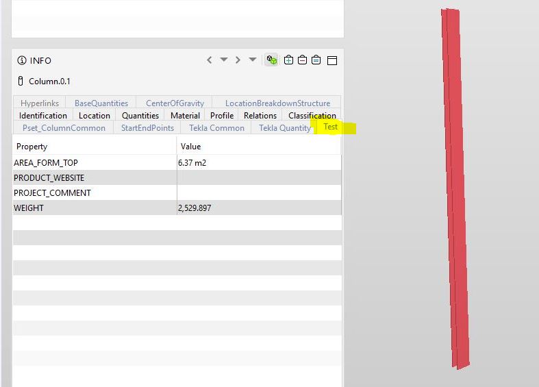
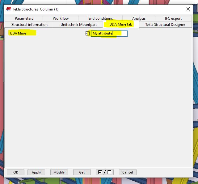
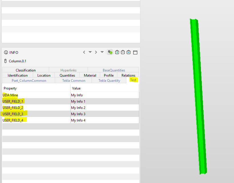
Tekla Structures has predefined sets of IFC object properties, but sometimes we need to export an object with attributes that are not included in the standard set. You can modify the standard set of properties by adding the attributes you need. In this case, I created an additional set (Test) with random attributes for this article. An additional tab called test appears in the exported object.
However, you can create your own sets, depending on your needs. What does it mean? Many companies create their own User defined attributes for the needs of projects or internal procedures. These attributes are assigned to objects in the model and are presented in drawings or reports. To also export as an object information set to an IFC model, you need to create additional export property sets.
Property sets are saved in an xml file, so they can be placed in project folders (PROJECT FOLDER) or in a firm folder (FIRM FOLDER) / about the folder structure in Tekla Structures, you can read here (http://bimcorner.com/pl/co-powinienes -wiedziec-before-work-z-tekla-structures /)
Additional sets of properties are extremely important when the project we work with is a non-drawing project. Thanks to this, the IFC model, which is the end product, includes all the information that is normally shown in the drawings.
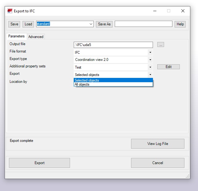
5. Select what you are exporting
The entire model is not always exported. Sometimes only a part of the facility, section, floor or several elements is enough.
6. Location by
This is a very important issue from the point of view of coordinating models from different industries. In order for BIM multi-discipline coordination to work as it should, it is extremely important to correctly position the models in relation to each other. Models must have the same coordinates. Projects are usually created in the right coordinates. Model builders, on the other hand, do not run correctly when model objects are too far from the local base point. Base points (control points) allow you to use a coordinate system based on a warp point or other coordinate system for interoperability and collaboration with other industries. The base point information is saved with the project properties.
AFTER EXPORT
Before sending the model for coordination or as reference to an architect or MEP designer, check that everything is okay. How to do it? In a very simple way. Import IFC as reference model back to Tekla. This will allow you to visually check whether the model is in the right position, whether any element is missing. Of course, you won’t find a small metal plate or a set of bolts missing, but sometimes errors can occur during export and even larger components may not be exported.
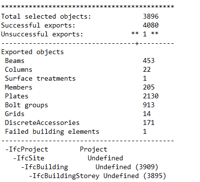
It is also worth taking a look at the LogFile, where you can find all information about the export and any errors.
SUMMARY
When working on interdisciplinary projects, export to IFC accompanies us probably more often than traditional printing. This is a good trend, considering that more and more projects are non-drawing projects. Therefore, a well-made export to IFC is an essential part of the design process. Knowing the rules, purpose and how to export from different construction software is so important.







Great for us non-Tekla users!
is there a reason not to use IFC4? The “advanced” tab shown in IFC export dialog is not shown in IFC4, so I’d like to know how to use IFC4 and not include rebar in my export.
IFC4 seems too new for full support eg. in Tekla Structures to be able to convert IFC objects again to native objects.
To control the export of rebar in your export (IFC2x3), simply go to the next tab “Advanced” and check/uncheck the “Reinforcing bars” box. Similarly in IFC4 export, you have expandable “Object types” in the bottom of the IFC4 Export dialog box, just expand it and check/uncheck the Reinforcing bars option.